1.2.3. Configuring an RS-485 communications network
1.2.3.1. Example of networking
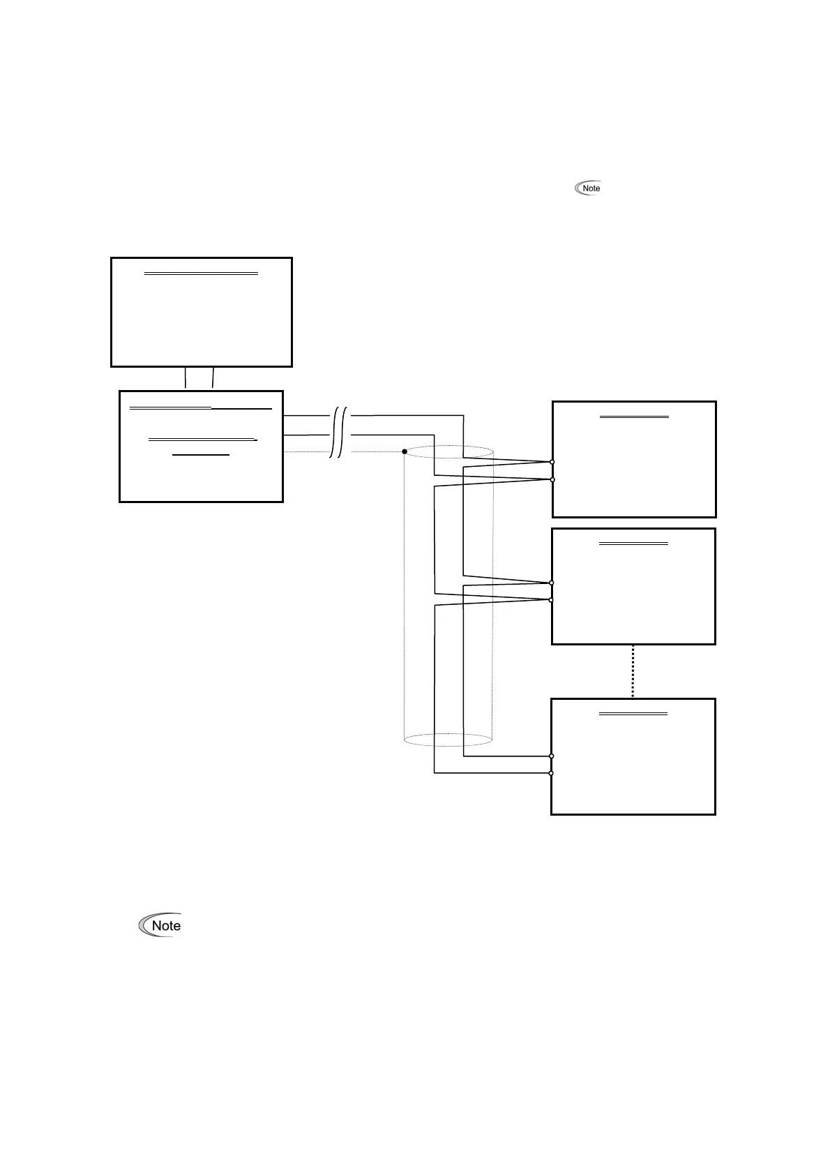
To configure an RS-485 communications network connecting inverters and a Loader-running PC,
use a Shielded twisted pair cable for long distance transmission. (See
below.)
FRENIC Loader VG
USB or RS-232C
TXD RXD
USB / RS-485 converter
or
RS-232C
/ RS-485
converter
Commercial item
(2-wire)
FRENIC-VG
Inverter 1
DX+
DX-
FRENIC-VG
Inverter 2
DX+
DX-
FRENIC-VG
Inverter n
DX+
DX-
Shield
Station address
:01
Use internal termination resistors
SW4
112 ohm
MAX. 31
2-wire
2-wire
Station address
:n
2-wire
Station address
:02
Figure 1.2.3-1 RS-485 Multi-drop Network (Terminal Block Connections)
When selecting communications support devices that protect parts on the printed
circuit boards of inverters from damage or malfunction due to external electrical noise
or to keep the network in high noise immunity level, carefully read through the
descriptions in FRENIC-VG user's manual Section 5.1.4 "Communications suppor
devices for RS-485".
When you connect the FRENIC Loader VG with FRENIC5000VG7S series, please
refer to Chapter 6 of FRENIC5000VG7S USER'S MANUAL.
4

 Loading...


