3-28
Section 3 Specications
3-7-4 Ethernet communication board (NA3LA-ET1) /
Ethernet communication unit (NA0LA-ET1)
(1) Specications
Item Specications
Interface 10BASE-T 100BASE-TX
Transmission speed 10 Mbps 100 Mbps
Medium (physical specication) IEEE802.3u
AUTO MDI/MDI-X Not supported
Interface changeover system Auto negotiation (automatic changeover)
Transmission medium Twisted pair cable
Max. segment length 100m
Max. number of nodes 1 node / segment
Communication
function
General purpose
communication
Communication between the PLC and other nodes is performed by using TCP/IP
or UDP/IP protocol. Because of free data format, it is possible to communicate with
all kinds of nodes.
Loader communication
(Server operation)
Communication with a POD or loader, host PC is performed by a loader command.
No communication program is required on the PLC side.
Loader communication
(Client operation)
The data memory in the target device (another SPH or SPF) is read or written.
“R_READ” (for reading data) and “R_WRITE” (for writing data) FBs are used for
communication.
Start these FBs to send or receive a loader command from the self station to the
target device.
Access method CSMA/CD
Transmission protocol TCP/IP, UDP/IP, ICMP (TYPE = 0, 3, 8), ARP
Max. number of simultaneous
communicable nodes
(number of communication ports)
8 stations / physical port
Note: The maximum number of communication ports that one CPU can
simultaneously open is 16 when using both an Ethernet front board and a
left side unit.
However, responses of communication deteriorate as the number of
communication ports per CPU increases.
Transmission code Binary only
Internal current consumption NA3LA-ET1: DC5V **mA, NA0LA-ET1: DC5V **mA
Occupied words 0 word
Ethernet status indication LED
Ethernet connector
Ethernet status indication LED
Ethernet connector
* For the detailed specications of and how to use the Ethernet communication board (NA3LA-ET1) and Ethernet communication
unit (NA0LA-ET1), refer to the user’s manual “SPF Ethernet Communication (FEH630).”
* Screw tightening torque for mounting the board on a main unit: 0.2 N·m
(2) Names
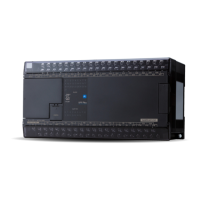
<NA3LA-ET1>
 Loading...

