Functions
Digital
input
[X1]
Digital
input 1
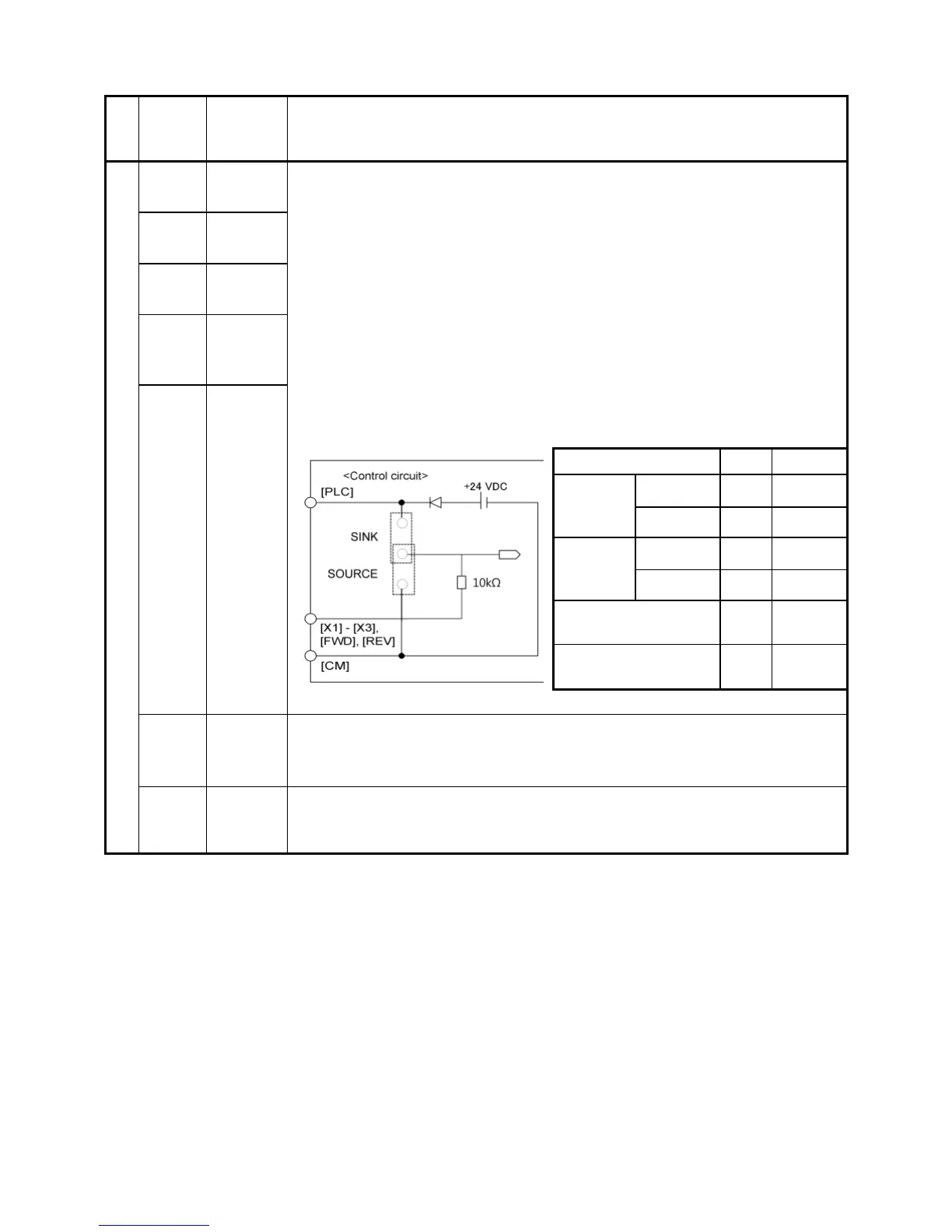
(1) The various signals such as "Coast to a stop," "Enable external alarm
trip," and "Select multistep frequency" can be assigned to terminals [X1] to
[X3], [FWD] and [REV] by setting function codes E01 to E03, E98, and E99.
For details, refer to Chapter 5, Section 5.2 "Details of Function Codes."
(2) Input mode, i.e. Sink/Source, is changeable by using the internal jumper
switch.
(3) Switches the logic value (1/0) for ON/OFF of the terminals between [X1] to
[X3], [FWD] or [REV], and [CM]. If the logic value for ON between [X1] and
[CM] is 1 in the normal logic system, for example, OFF is 1 in the
negative logic system and vice versa.
(4) The negative logic signaling cannot be applicable to [FWD] and [REV].
[PLC]
PLC
signal
power
Connects to PLC output signal power supply.
Rated voltage: +24 VDC (Allowable range: +22 to +29 VDC), Max. 50 mA
[CM]
Digital
common
Common terminal for digital input signals
This terminal is electrically isolated from terminals [Y1E].