Table 2.7 Symbols, Names and Functions of the Control Circuit Terminals (Continued)
Functions
Digital I
nput
Using a relay contact to turn [X1], [X2], [X3], [FWD] or [REV] ON or OFF
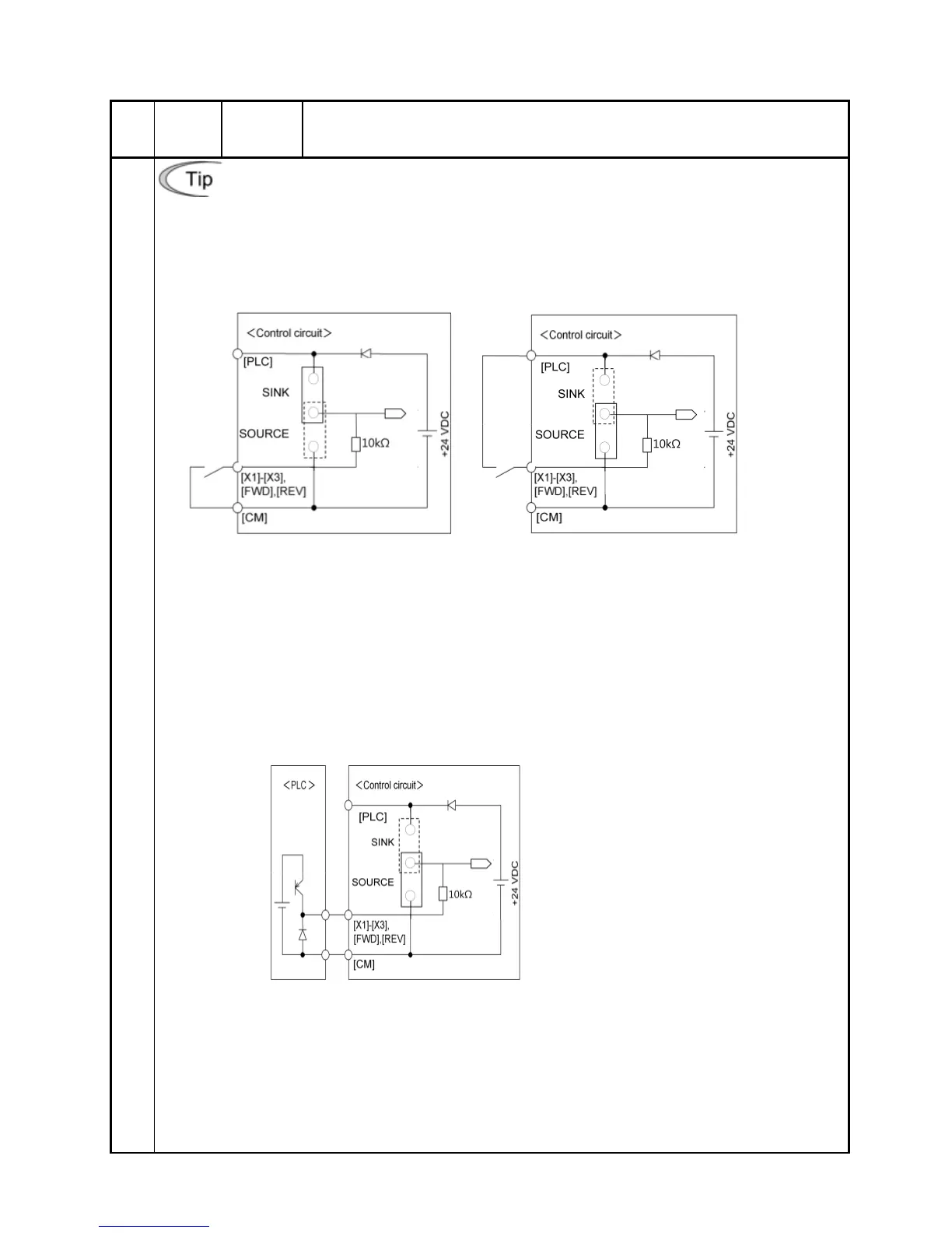
Figure 2.7 shows two examples of a circuit that uses a relay contact to turn control signal
input [X1], [X2], [X3], [FWD] or [REV] ON or OFF. Circuit (a) has a connecting jumper
applied to SINK, whereas circuit (b) has one that is applied to SOURCE.
Note: To configure this kind of circuit, use a highly reliable relay.
(Recommended product: Fuji control relay Model HH54PW)
(a) With a jumper applied to SINK (b) With a jumper applied to SOURCE
Figure 2.7 Circuit Configuration Using a Relay Contact
Using a programmable logic controller (PLC) to turn [X1], [X2], [X3], [FWD] or
[REV] ON or OFF
Figure 2.8 shows example of a circuit that uses a programmable logic controller (PLC)
to turn control signal input [X1], [X2], [X3], [FWD] or [REV] ON or OFF. Circuit (a) has a
connecting jumper applied to SOURCE.
In circuit (a) below, short-circuiting or opening the transistor's circuit in the PLC using an
external power source turns control signal [X1], [X2], [X3], [FWD] or [REV] ON or OFF.
(a)
With a jumper applied to SOURCE
Figure 2.8 Circuit Configuration Using a PLC
For details about the jumper setting, refer to Section 2.3.7 "Setting up the jumper switches."