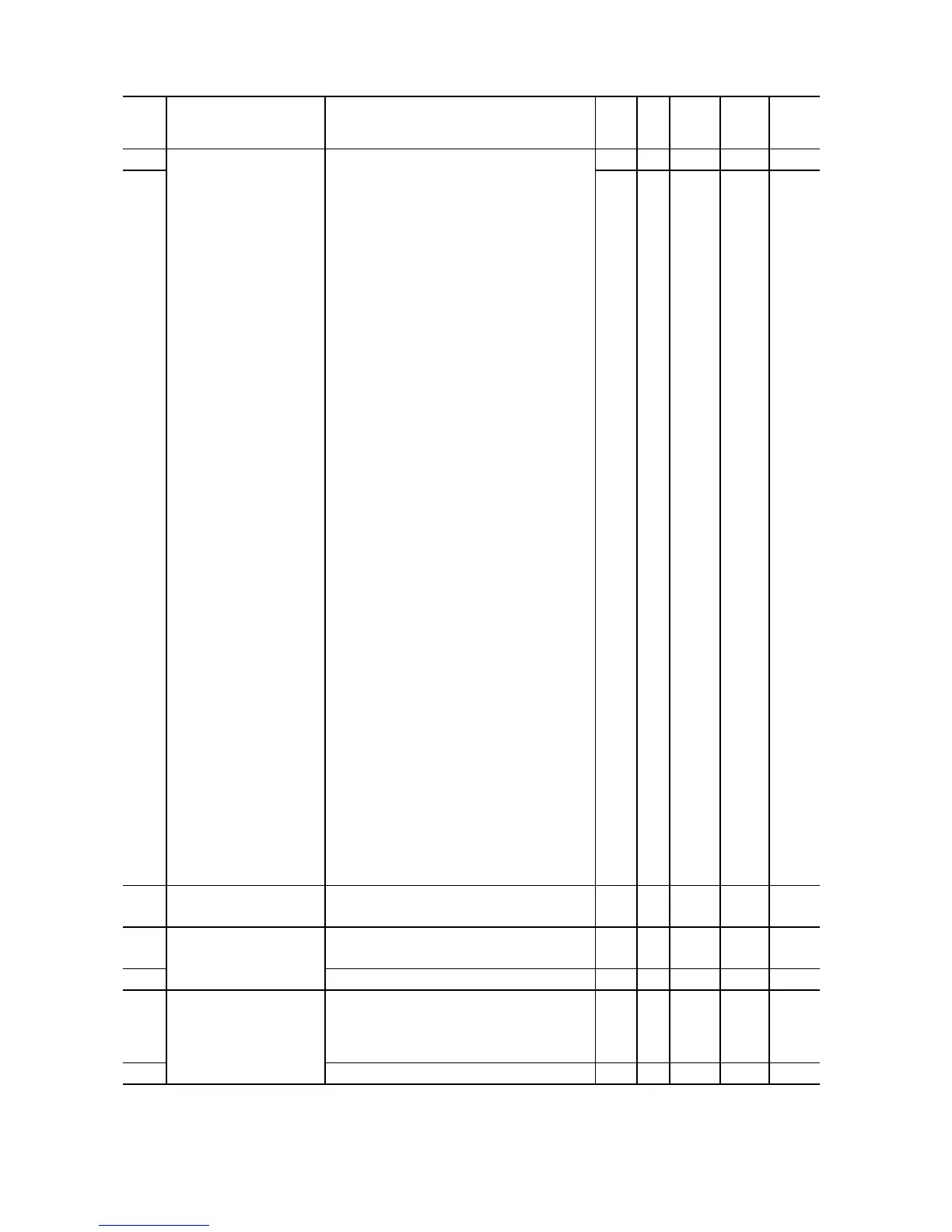
Data setting range
Incre-
Terminal [30A/B/C]
Function
Selecting function code data assigns the
corresponding function to terminals [Y1] and
[30A/B/C] as listed below.
0 (1000): Inverter running (RUN)
1 (1001): Frequency arrival signal (FAR)
2 (1002): Frequency detected (FDT)
3 (1003): Undervoltage detected
(Inverter stopped) (LU)
5 (1005): Inverter output limiting (IOL)
6 (1006): Auto-restarting after momentary
power failure (IPF)
7 (1007): Motor overload early warning
(OL)
26 (1026): Auto-resetting (TRY)
35 (1035): Inverter running 2 (RUN2)
36 (1036): Overload prevention control
(OLP)
37 (1037): Current detected (ID)
38 (1038): Current detected 2 (ID2)
41 (1041): Low current detected (IDL)
43 (1043): Under PID control (PID-CTL)
44 (1044): Motor stopped due to slow
flowrate under PID control
(PID-STP)
56 (1056): Motor overheat detected by
thermistor (THM)
57 (1057): Brake signal (BRKS)
59 (1059): Terminal [C1] wire break
(C1OFF)
84 (1084): Maintenance timer (MNT)
87 (1087): Frequency arrival detected
(FARFDT)
90(1090): Traverse Up (TRV_UP)
91(1091): Traverse Out (TRV OUT)
99 (1099): Alarm output (for any alarm)
(ALM)
Setting the value in parentheses ( ) shown
above assigns a negative logic output to a
terminal.
E30 Frequency Arrival
(Hysteresis width)
0.0 to 10.0 0.1 Hz Y Y 2.5
(Detection level)
(Hysteresis width)
E32 0.0 to 400.0 0.1 Hz Y Y 1.0
E34
Overload Early Warning/
Current Detection/Low
Current Detection
(Level)
0.00 (Disable), 0.01 to 100.0
Current value of 1 to 200% of the inverter
rated current
0.01 A Y
Y1
Y2
See
Table
A.
*1 When you make settings from the keypad, the incremental unit is restricted by the number of digits that the LED
monitor can display.
(Example) If the setting range is from -200.00 to 200.00, the incremental unit is:
"1" for -200 to -100, "0.1" for -99.9 to -10.0 and for 100.0 to 200.0, and "0.01" for -9.99 to -0.01 and for 0.00 to 99.99.