¢
Specifications
Unit: mm
86
86 32
Hole × 2 (for M4 screws)
60
Size (H × W × D) mm 86 × 86 × 32
Weight g 135
Wiring specifications
Use Cable size Wire type Remarks
Remote controller
cable
0.33 to 1.25 mm
2
(22 to 16 AWG)
Non polar 2-core Use sheathed twist pair cable.*
*: Use shielded cable (locally purchased) in accordance with the regional cable standard.
¢ Installation
• Connection pattern
NOTE: Connection pattern is different according to type of Indoor unit.
Indoor unit type Connection pattern
All cassette type Pattern A
All duct type Pattern A
Compact floor type Pattern A
Wall mounted type Pattern B
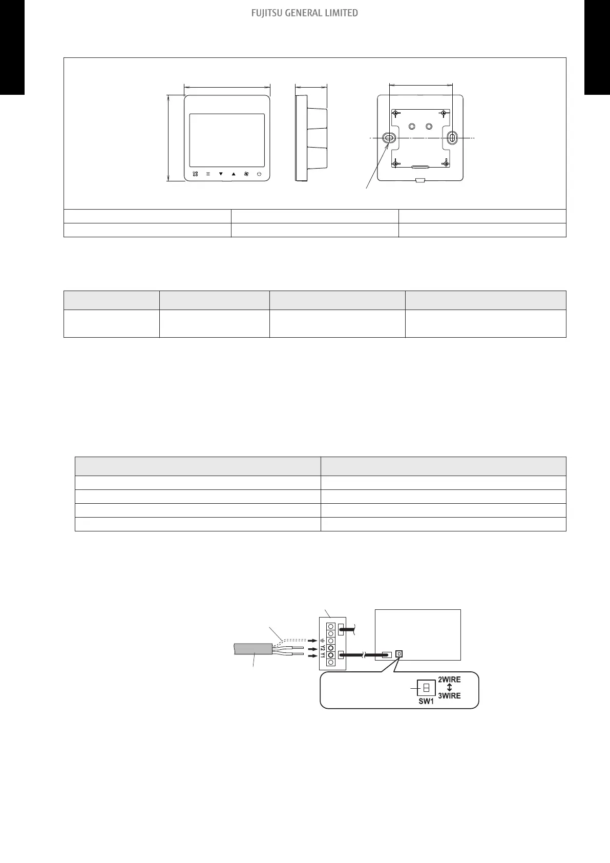
• Pattern A
1. Connect the end of remote controller cable directly to the exclusive terminal block.
2. Set the DIP switch (SW1) to “2WIRE” on the PCB of the indoor unit.
Terminal block
Functional grounding
(If necessary)
Remote controller cable
(Non-polar)
Indoor unit PCB
Set the DIP switch
(SW1) to “2WIRE”
NOTES:
• Layout of terminal block and PCB is varies depending on the type of indoor unit.
• Operation may fail if it is connected to the outdoor unit or the terminal block for power
supply.
- 205 -
14-11. Wired remote controller (UTY-RCRYZ1: Optional part) 14. Remote controller
2-UNIT
MULTI-SPLIT TYPE
2-UNIT
MULTI-SPLIT TYPE
 Loading...