EasyManua.ls Logo

Fukuda FL-286 - Remote Terminal Board and Signals; Control Signal Definitions; Cylinder and Group Control Signals

Default Icon
35 pages
Print Icon
To Next Page IconTo Next Page
To Previous Page IconTo Previous Page
Loading...
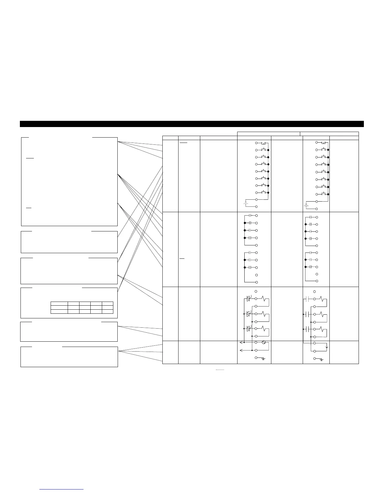
ELECTRIC WIRING CONFIGURATION
Control testing and bubble testing procedures
START Start of air leak test.
Applies a pulse signal of 0.5 sec or longer during DLY sequence.
BUBL Start of bubble test
Performs a bubble test while a signal is being applied.
RESET Stop the tester in case of an emergency.
Apply a break signal to open the air circuit. The RDY sequence
is established after EXH sequence.
Test result output
OK -NG set range leak reange +NG set range
+NG leak reange +NG set range
-NG -NG set range leak reange
P.NG Test pressure is lower than the set value at the end of
PRES sequence.
P.NG Test pressure is lower than the set value set up with
P.SW at time of BAL sequence.
Current status output
RDY Standby (Ready Status)
ERR Error has transpired.
When the power is OFF, ERR can be used to confirm
ON/OFF status.
END Testing has ended.
1 The air leak tester’s internal output status: power off.
2 The names, indicated with line(***)imply that the signal is effective when it is open. 19
Controlling clamping cylinders
LMT 1 Input of unclamp signals
LMT 2 Input of clamp signals
SOL 1 Cylinder Driving valve control signals
In the Internal Operation Mode, the tester cannot operate.
Specifies the Group # (03)
CH1
CH2
Group # selection
0 1 2 3
CH1
CH
2
○:Open ●:Short
Controls the exhaust bypass unit
SUPPLIES POWER TO THE AIR LEAK TESTER
Apply power voltage specified by the manufacture
F.G Be sure to ground this terminal.
EXHAUST BYPASS UNIT CONTROL SIGNALS
POWER SUPPLY
GROUP SWITCHING SIGNALS
CYLINDER CONTROL SIGNALS
Pressure Error (P.NG) Verification Signal Input
P.SW Pressure switch signal input.
If pressure verification function is not used,
keep the P.SW pin connected to the COM- pin.
PRESSURE VERIFICATION SIGNALS
AIR LEAK TESTER CONTROL SIGNAL
z REMOTE TERMINAL BOAR
FL-
2
□□□-
0
FL-
2
□□□-
2
N
o
Cod
e
Meanin
g
Connection *1 Specification Connection *1 Specification
1
2
3
4
5
6
7
8
9・10
11・12
RESET
START
BUBL
P.SW
LMT1
LMT2
CH1
CH2
COM-
COM+
Reset signal
Measurement start signal
Bubble test
Pressure verification
Unclamp verification
Clamp verification
Group # switch
Group # switch
Input signal common
Power sup. for pres. switch
Input si
g
nal
(Photo coupler)
Voltage when open
DC 12V type
Voltage when
shorted
5 mA type
COM+Power
Supply
Output voltage
DC 12V type
Output current
50 mA min
Input si
g
nal
(Photo coupler)
Voltage when
open
DC 12V type
Voltage when
shorted
5 mA type
COM+Power
Supply
Output voltage
DC 12V type
Output current
50 mA min
13
14
15
16
17・18
19
20
21
22
23・24
OK
+NG
-NG
P.NG
COM O
1
RDY
ERR
END
COM O
2
OK results output
+NG result output
-NG result output
Pressure malfunction. Output
Output signal common 1
Stand by (Ready) output
Error output
End output
Unconnected
Output signal common2
Output si
g
nal
(Relay contact)
Rated load
AC 250V 0.4A
DC 30V 0.4A
Output si
g
nal
(Relay contact)
Rated load
AC 250V 0.4A
DC 30V 0.4A
25・26
27
28
29
30
31
32
SOL1
SOL1
SOL2
SOL2
SOL3
SOL3
Unconnected
Cylinder drive valve output
Pressure valve output
Optional valve output
Output si
g
nal
(SSR)
Output Voltage
Power source
supply
Actual ON current
1.0 Arms
Leak current
3 mA max
Output si
g
nal
(Relay contact)
Rated load
AC 250V 1A
DC 30V 1A
To accord with
external supply
power source specs.
33・34
35・36
37・38
AC
AC
F.G.
AC power input
AC power input
Frame Ground
Power source for
tester
AC100V±10%
50/60Hz
(Used also as external
valve power source)
Power source for
external valve
AC100V
DC24V
(Power source for
tester is inlet.)

Related product manuals