ELECTRICAL AND AIR PIPE LINE CONNECTIONS
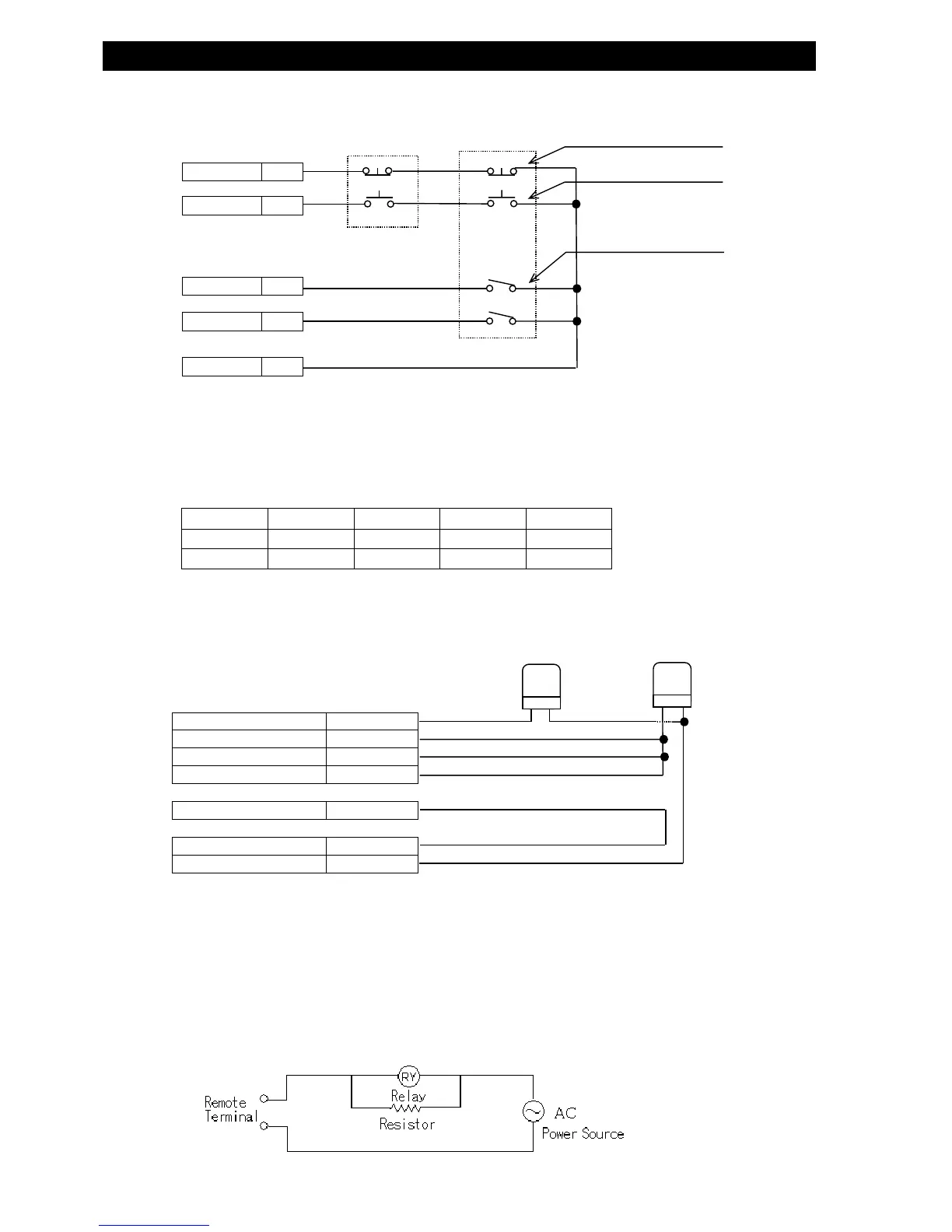
● CONTROL BY LEFT/RIGHT HAND SWITCH
z The operation procedure for the above connection is described as below:
・Emergency Stop: Press either one of the two reset switches.
・Start Testing: Press both START switches simultaneously.
・Bubble Test: Press the Bubble Test switch.
z The bubble status continues to output while the switch is engaged.
・Group Selection: Select the group # and set the switch to the number.
0 1 2 3
SWITCH① ○ ● ○ ●
SWITCH② ○ ○ ● ●
○:OFF ●:ON
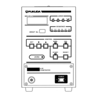
● DRIVING EVALUATION INDICATOR
z The external alarm lamp is illuminated by the Air Leak Tester evaluation signal.
The example shown above is the connection to light Green lamp for OK (accepted), and Red lamp for
+NG、-NG、P.NG (rejects and error).
z The load capacity should be kept within the rated value(Rated load: AC 125 V 0.4A DC 30V 0.4A)
z
When connecting to the direct voltage to output signal line, and the relays and other devices are malfunctioning,
provide a resistance in the circuit as shown in the diagram below. The Remote terminal output is equipped with
a noise suppressor, and it may generate a leak current when it is turned off (Estimated leak current: 3mA Max
for AC100V 60Hz)
BLUE LAMP RED LAMP
RESET 1
START 2
CH1 7
CH2 8
COM- 9・10
LEFT SWT RIGHT SWT
RESET SWITCH
START SWITCH
GROUP SELECT
SWITCH
①
②
OK
13
+NG 14
-NG 15
P.NG 16
COM O
1
17・18
AC & DC12V COM+ 35・36 & 11・12
AC & DC12V COM- 33・34 & 9・10