ELECTRIC WIRING CONFIGURATION
● ELECTRIC WIRING PRECAUTIONS
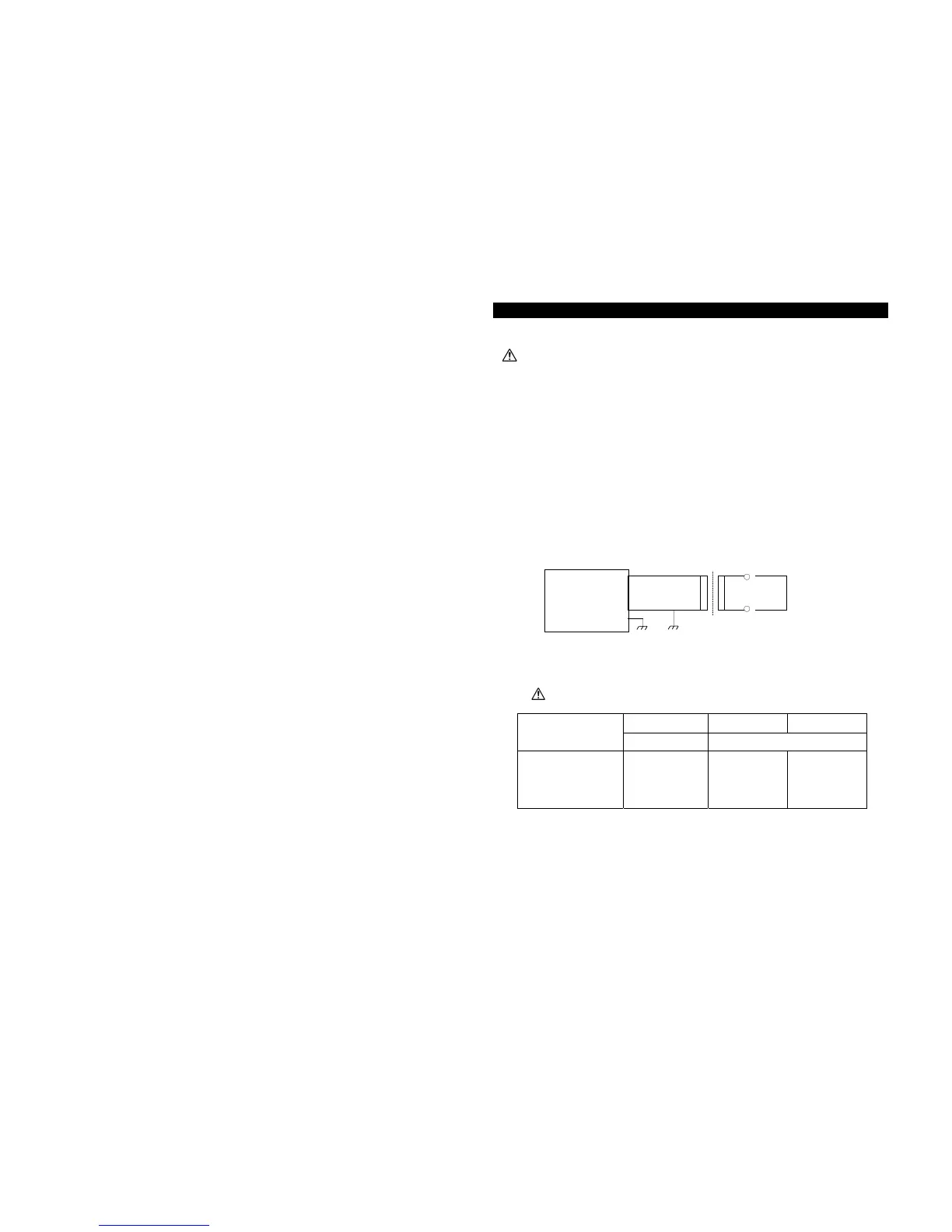
EXAMPLE
(AC 200V/100V step-down transformer is used for an air leak tester with AC 100V spec)
Air Leak Tester
MODEL
AC100V AC110V AC200V
FL-2□□□-0 FL-2□□□-2
POWER LINEVOLTAGE
AC100V±10%
50/60 Hz
AC90~110V
50/60 Hz
AC200~240V
50/60 Hz
※ Power consumption increases if valves and other parts are driven by an external control.
18
AC100V
BEFORE WIRING AIR LEAK TESTER, BE SURE TO TURN OFF THE MAIN POWER
SWITCH. (Unplu
)
Insulated Transformer
AIR LEAK TESTER with AC100V
Supply line voltage suitable to the power line voltage of the tester.
● Select appropriate wires and material according to use, considering voltage and current
requirements for each of the terminal outlets located on the rear panel of the tester.
● To avoid noise interference, run the input signal lines separately (pins #1 to #12 of the Terminal Board)
from the output signal lines.
● To avoid noise interference, run the input signal lines separately from other power supply lines.
● To avoid noise interference, it is recommended to use a shield wired for input signal lines.
● Be sure to ground the frame grounding (pins #37 and #38 of Terminal Board).
● Use an insulated transformer when the power for the tester is supplied through a step-down
transformer.
AC200V
AC100V L
AC100V N
F.G.
○
○