EasyManua.ls Logo

Fukuda FL-286 - User Manual

Default Icon
35 pages
Print Icon
To Next Page IconTo Next Page
Loading...
10527-T-800E-00
http://www.fukuda-jp.com
COMPACT AIR LEAK TESTER
DESIGN DOCUMENT
FL-296 SERIES
Contents
MODEL ・・・・・・・・・・・・・・・・・・・・・・・・・・・・・・・・・・・・ 6
SPECIFICATIONS ・・・・・・・・・・・・・・・・・・・・・・・・・・・・・ 7
DO YOU HAVE EVERYTHING? ・・・・・・・・・・・・・・・・・・・・・・・ 8
OPTION ・・・・・・・・・・・・・・・・・・・・・・・・・・・・・・・・・・・・ 9
INSTALLATION INSTRUCTIONS ・・・・・・・・・・・・・・・・・・・・ 14-15
AIR PIPE CONFIGURATIONS ・・・・・・・・・・・・・・・・・・・・・・ 16-17
ELECTRIC WIRING CONFIGURATIONS ・・・・・・・・・・・・・・・・・ 18-19
LINE CONNECTIONS ・・・・・・・・・・・・・・・・・・・・・・・・・・・・・ 20-35
RS-232C CONNECTION ・・・・・・・・・・・・・・・・・・・・・・・・・・ 60-63
PRINTER CONNECTIONS ・・・・・・・・・・・・・・・・・・・・・・・・ 65
EXTERNAL DIMENSIONS ・・・・・・・・・・・・・・・・・・・・・・・・ 72-74
Declaration
This design documents is outline specification for system design which is extracted from operation manual
(10527-T-001E-05).
The above contents page numbers is mentioned the page numbers of operation manual.
For about details of operation and testing procedure, please refer to operation manual.
The contents of this manual may be modified without notice due to function and performance improvements.
This manual has been written with care to provide the user with helpful and useful information. Please
contact your local FUKUDA distributor if there are any inaccuracies or questions of concern.
Do not use this tester for any purpose other than testing air leaks.
For best operating results and optimum efficiency, read this instruction manual thoroughly
to understand the tester’s many functions prior to operation.
Reprinting or duplicating this manual partially or completely is prohibited unless permitted by
FUKUDA CO., LTD.
Trademark
Company names and product names being used in this manual are the registered trademarks of
their respective holders.
Question and Answer IconNeed help?

Do you have a question about the Fukuda FL-286 and is the answer not in the manual?

Summary

Outline Tester Model

Model Identification

Details the model number breakdown based on components.

Tester Specifications

Performance Specifications

Details leak pressure range and measurement sensor accuracy.

Function Specifications

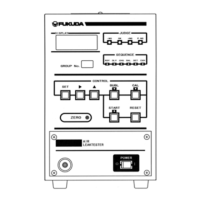
Covers timer settings, group settings, display, and input/output.

General Specifications

Includes operating environment, power, dimensions, and air specifications.

Options

Installation Instructions

Installation Safety Warnings

Covers crucial warnings and cautions for safe installation of the tester.

Operation Environment Requirements

Specifies temperature, humidity, and location guidelines for optimal performance.

Installation Layout and Measurement

Air Pipe Configurations

Air Piping Configuration

Compressed Air Source Requirements

Emphasizes clean air and filtration for sensor integrity.

Electric Wiring Configuration

Wiring Precautions and Safety

Covers safety and noise reduction tips for electrical wiring.

Power Supply Voltage Connections

Details wiring for different power supply voltage models.

Remote Terminal Board and Signals

Control Signal Definitions

Explains signals for testing, results, and status indicators.

Electrical and Air Pipe Line Connections

Leak Side Testing (Outside Pressure)

Diagram and specs for external pressure leak testing.

Leak Side Testing (Internal Pressure)

Diagram and specs for internal pressure leak testing.

Vacuum Leak Testing Connections

Vacuum Source Method Setup

Diagram and specs for vacuum testing using a source.

Vacuum Ejector Method Setup

Diagram and specs for vacuum testing using an ejector.

Connecting Exhaust Bypass Units

Pressure Verification Switch Connections

Work Clamping Cylinder Control (Limit Switches)

Limit Switch Wiring and Specs

Wiring, load voltage, and power consumption for limit switches.

Clamping Cylinder Operation Timing

Explains the sequence of operations for cylinder clamping.

Work Clamping Cylinder Control (DLY Timer)

Solenoid Valve Specifications

Driving voltage and power consumption for solenoid valves.

DLY Timer Operation Timing

Describes the timing sequence for clamping/unclamping with a DLY timer.

PLC Connection and Control

Control Timing by PLC

RS-232 C Connection

Data Transmission Procedures

Fukuda FL-286 Specifications

General IconGeneral
CategoryTest Equipment
ModelFL-286
ManufacturerFukuda
DisplayLCD
Operating Temperature0°C to 40°C

Related product manuals