ELECTRICAL AND AIR PIPE LINE CONNECTIONS
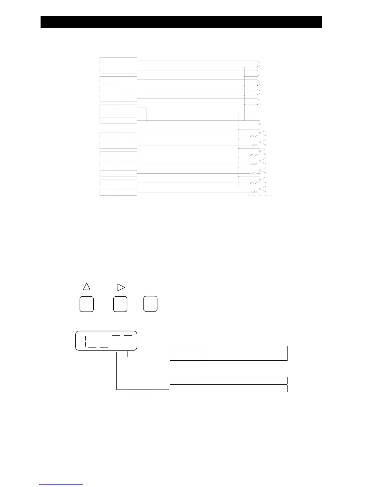
● CONNECTION WITH THE PLC (PROGRAM LOGIC CONTROLER
RESET 1
START 2
BUBL 3
CH1 5
CH2 6
COM- 9・10
COM O1 17・18
COM O2 23・24
OK 13
+NG 14
-NG 15
P.NG 16
RDY 19
ERR 20
END 21
24V
0V
シーケンサー
● The load capacity for the relays in tester should be maintained within the specified value( AC125V 0.4A
DC30V 0.4A).
● To control the work-clamping cylinder by PLC, input a measurement start signal after confirming the clamp of
the work.
● Preset the Air Leak Tester testing condition to:
・Set to condition setting status
SET
> >
DISPLAY
For test condition setting procedures details, refer to page 38.
ON
OFF
・PRESET THE CYLINDER CONTROL METHOD
SWITCH STATUS
ON CONTROL BY DLY TIMER
・PRESET THE PROPERTY OF THE START SIGNAL
SWITCH STATUS
ON
A PULSE OF ≧0.5seccond
PLC