ELECTRICAL AND AIR PIPE LINE CONNECTIONS
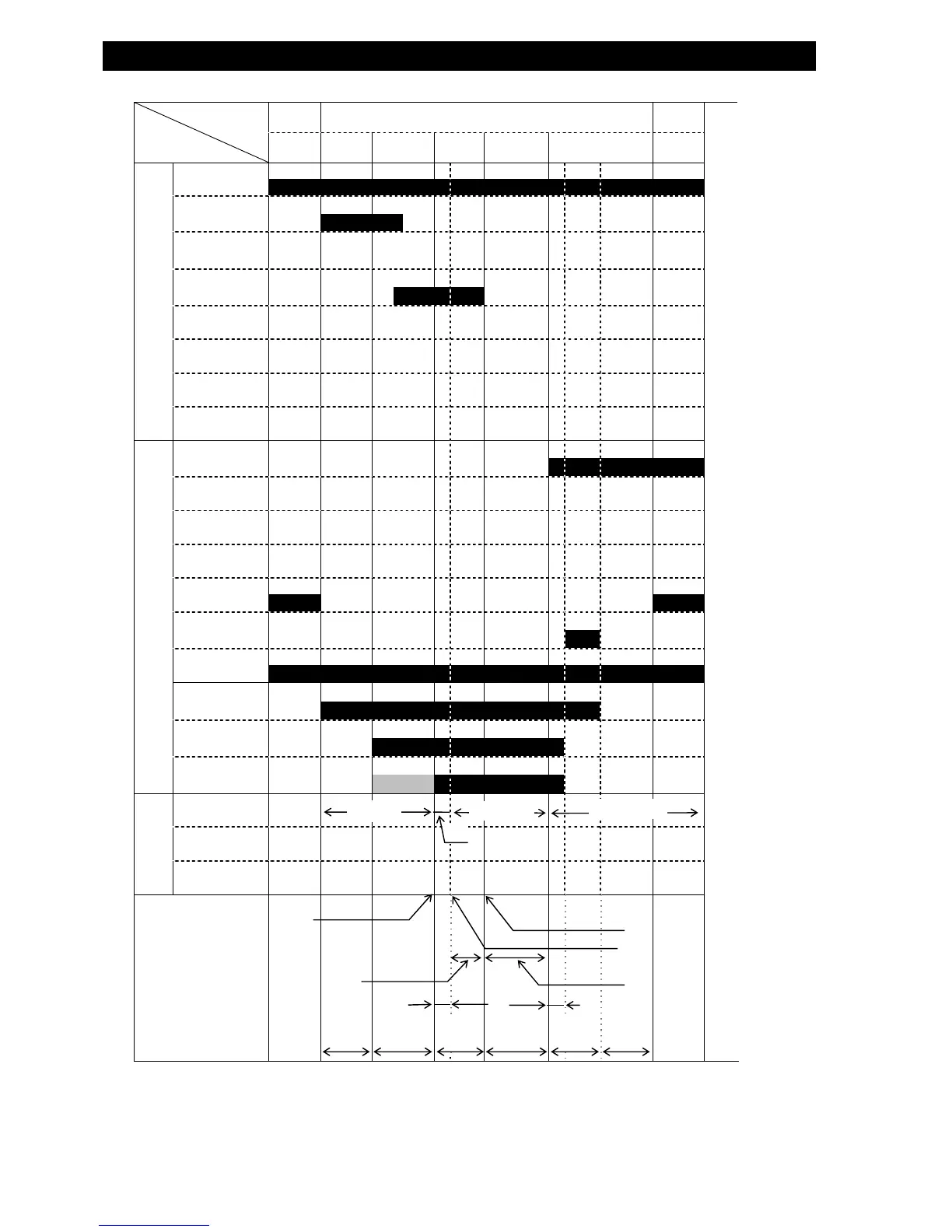
■ TIME CHART
PROCESS
ITEM
READY OK WORK EVALUATION READY
RDY DLY CHG BAL DET EXH RDY
INPUT
RESET
START
BUBL
P.SW
LMT1
LMT2
CH 1
CH 2
OUTPUT
OK
+NG
-NG
P.NG
RDY
END
ERR
SOL1
SOL2
SOL3
*2
OTHERS
MAIN DISPLAY
GROUP DISPLAY
BUZZER
REMARKS
DLY
TIMER
CHG
TIMER
DET
TIMER
DLY
TIMER
*1This time chart is for the following specifications:
・Cylinder control using the DLY timer.
・Upon NG detection in the DET sequence, EXH sequence immediately follows.
*2 With (-) sign in P.NG setting, SOL3 signal continues for a duration indicated by a light gray bar.
With (+) sign in P.NG setting, SOL 3 signal continues for a duration indicated by a light gray and black bar.
P.SW CONFIR.
ZERO CORRECTION
ZERO CORRECTION
L.LEAK DET.
S.LEAK DET.
0.6sec
0.1sec
BAL
TIMER
EXH
TIMER
OFF
DIF. PRES
VALUE HOLD
P.SW