ELECTRICAL AND AIR PIPE LINE CONNECTIONS
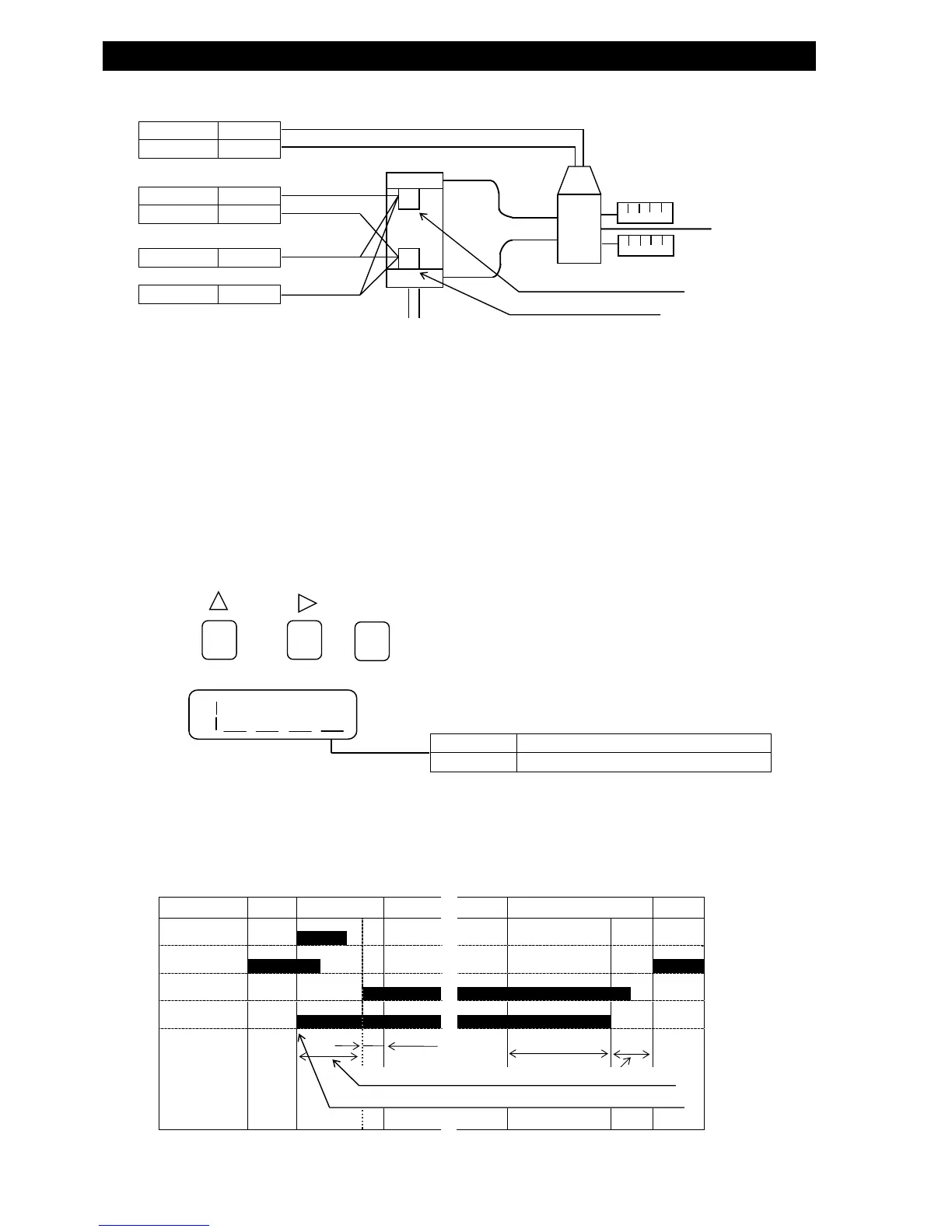
● WORK CLAMPING CYLINDER CONTROLLED BY LIMIT SWITCHES
SET
> >
DISPLAY
For further details of the test condition setting procedures, refer to page 38.
● Operation timing is as follows:
・Set the DLY timer to delay pressure applying timing (①).
・Error 5 and 6 functions are only controllable via REMOTE connector.
RDY DLY CHG DET EXH RDY
START
LMT1
LMT2
SOL1
①
0.5sec
EXHSETTINGTIME
※ In the Internal Operation Mode, the tester cannot run.
SOL1 27
SOL1 28
LMT1 5
LMT2 6
COM- 9・10
COM+ 11・12
①
WORK CLAMPING CYLINDER
CYLINDER
CONTROL VALVE
②
③
◎
UNCLAMPING SWITCH
CLAMPING SWITCH
ON
OFF
・PRESET THE CYLINDER CONTROL METHOD
SWITCH STATU
ERROR5: (UN)CLAMPING NOT COMPLETED AFTER 3 MIN.
ERROR6: NO LMT1 SIGNAL AT THE STARTING TIME
∬
∬
● Connect + line to ①, and -line to ②. For a 3-wire cylinder, connect power line to ③.
● Choose limit switches that fulfill the following specifications:
・ Load (power) voltage: DC12V
・ Power Consumption (for 3-wire switch): 50mA or less for the total of the load connected to COM +
・ Load current: 5mA
・ Voltage Drop: Less than 3V
・ Leakage Current: Less than 1mA
● Choose solenoid valves for cylinder controls that fulfill the specifications indicated below:
・Driving Voltage : FL-2□□□-0:AC100V 50/60HZ
FL-2□□□-2:To accord with external valve power source specs.
・ Power Consumption : Less than 100VA
・ Preset the Air Leak Tester testing condition to:
● Set to condition setting status.