1. MOUNTING
1-6
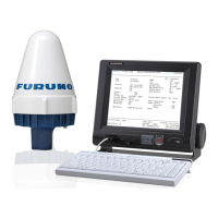
3) Refasten two screws removed at step 1) to fix the clamp.
4) Run the interconnection cable thorough a cable entrance and connect it to ter-
minal board.
Flush mount
The optional flush mounting kit OP16-27 (Code No.: 004-448-000) is required.
1. Make a cutout in the mounting location, referring to the outline drawings at the
back of this manual.
2. Fix the unit to the fixture with four pan head screws (supplied).
3. Fasten four self-tapping screws (φ5, supplied) to fasten the fixture to the mounting
position.
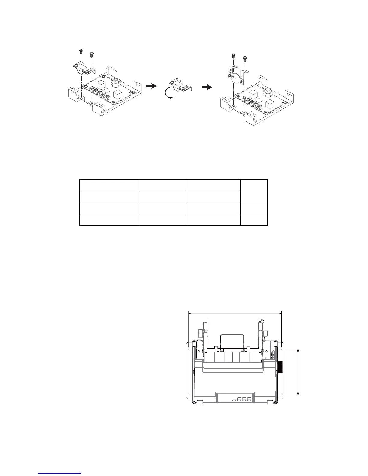
1.4 Printer (option)
Mount the printer (PP-510 or PP-520)
on a tabletop with the fixtures sup-
plied. Refer to the outline drawing at
the end of this manual for the mount-
ing dimensions. The right figure is for
PP-520
1. Decide the location of the printer.
2. Set the ink ribbon cartridge and
the roll paper to the printer.
3. Set the fixtures (left/right) onto
the printer. Fasten them with four
self-tapping screws (φ5x20).
Name Type Code No. Qty
Fixture 16-018-4201-1 100-317-841 1
Pan head screw M3x6 000-800-362 4
Self-tapping screw 4x16 000-162-605-10 4
Unfasten these screws.
Rotate.
Refasten screws.
405
200
 Loading...