1. MOUNTING
1-2
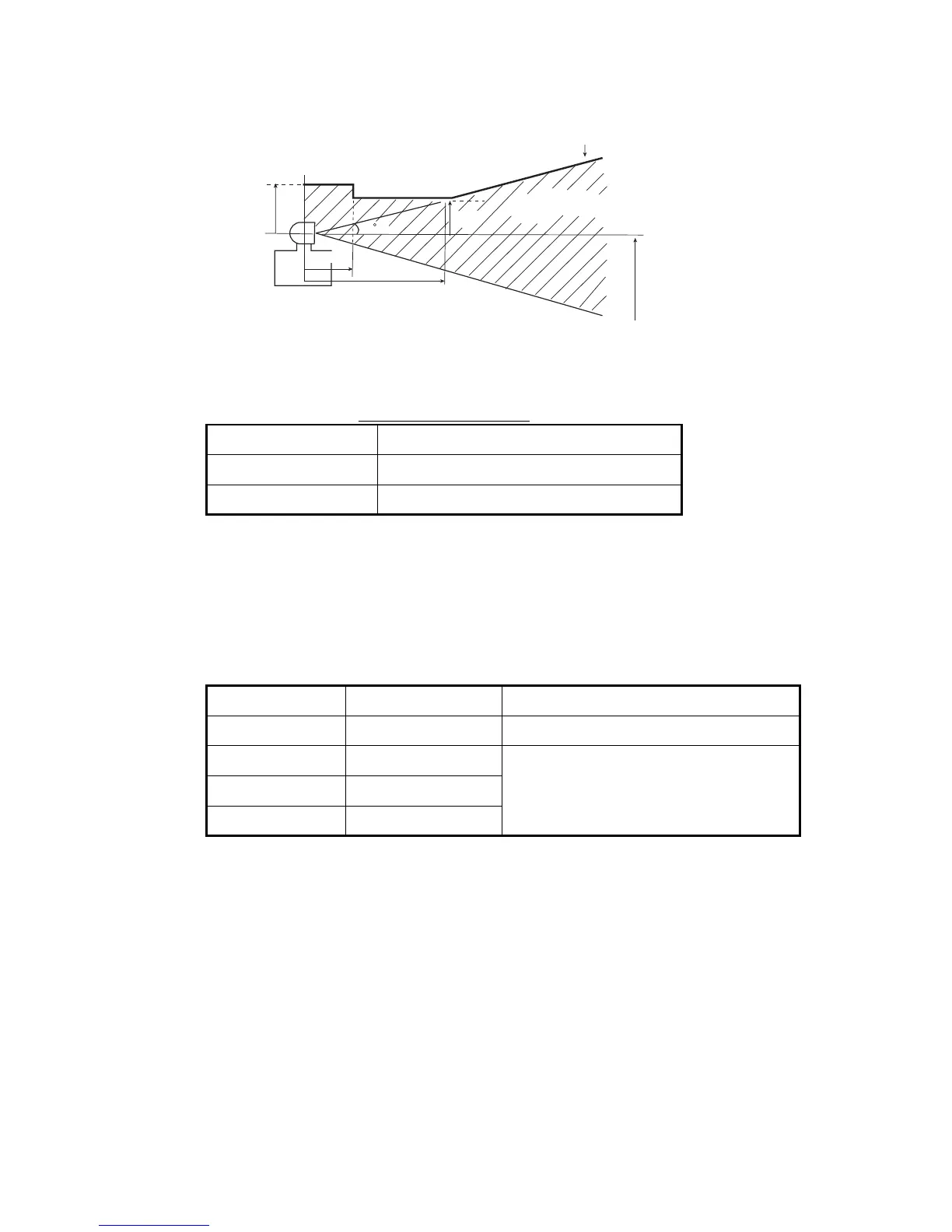
• Separate the antenna unit from an S-band radar as follows:
• The allowable vibration level as specified by Inmarsat is as shown in the table be-
low.
Allowable vibration level
• Avoid the location near tunnels and stacks; smoke and soot on the radome can low-
er signal level (10 m or more in horizontal distance).
• Separate the antenna unit 5 m from HF, VHF of 27 MHz antenna.
1.1.2 Mounting
The antenna cable is available in lengths of 30 m, 50 m and 100 m (see table below).
To mount the antenna unit, a dedicated mounting pipe is necessary.
For how to mount the antenna, see the outline drawing at the end of this manual and
“Installation and Replacement of Antenna Unit”, included with the antenna unit.
1.2 Terminal Unit
Select a mounting location, considering the following points.
• The temperature and humidity should be moderate and stable.
• For maintenance and checking purposes, leave sufficient space at the sides and
rear of the unit and leave slack in cables.
Frequency Level
2 to 10 Hz 2.54 mm Peak Amplitude
10 to 100 Hz 9.8 m/s2 Peak Acceleration
Cable length Type Remarks
30 m (no armor) TP5FBAW-5DFB TNC connector at both ends
30 m (w/armor) 5D-FB-CV-NP N connector on one end (antenna side)
50 m (w/armor) 8D-FB-CV
100 m (w/armor) 12D-SFA-LITE-CV
HORIZONTAL LINE
Install above this line
PROHIBITED
ZONE
1.5 m
5 m
15
2 m
S-band radar
INSTALLTION
ZONE
2 m
 Loading...