4-1
4. HOW TO INSTALL OPTIONAL
EQUIPMENT
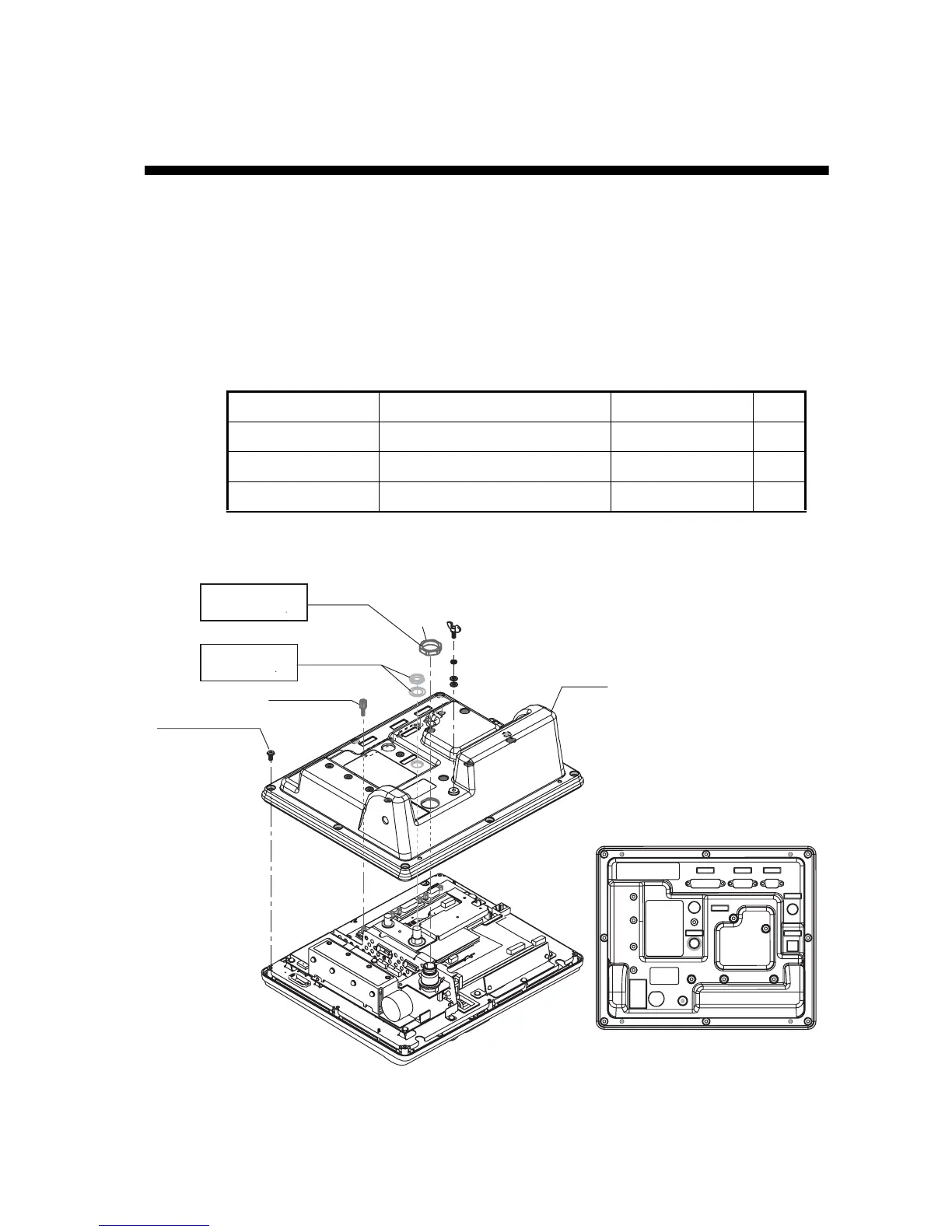
4.1 GPS Board OP16-62
This chapter provides the procedure for the installation of the GPS board (in the ter-
minal unit), which provides GPS position information.
Name: GPS board
Type: OP16-62
Code No.: 001-180-100
Note: Use anti-static gloves to handle board.
1. Unfasten 18 screws, six spacers and three nuts to remove the terminal unit cover.
2. Fasten three binding screws (M3x6, supplied with the kit) to attach the GPS Board
to the RF cover.
Name Type Code No. Qty
Binding Screw M3x6 000-163-479-10 3
GPS Board 16P0246 004-656-550 1
Connector Assy. 51065-0700-PHR7-L110 000-176-305-10 1
Cover
Spacer
6 pcs.
Nut,
flat washer
Pan head screw
M3x8, 18 pcs.
Torque
1.37±0.1 N m
Torque
0.76±0.02 N m
Rounding
side
*
*
*
*
*
*
*
*
*
*
****
*
*
*
*
*
**
*
*
*
*
*
*: Remove.
Nut
 Loading...