2. WIRING
2-6
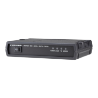
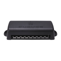
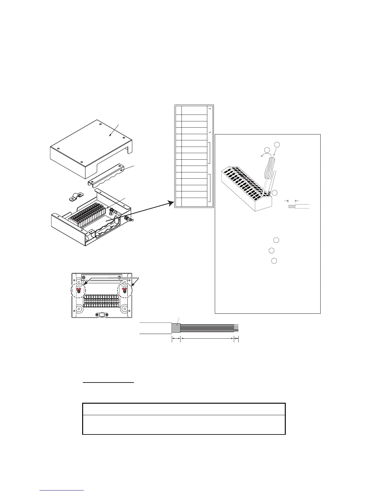
2.4 Junction Box IC-318
Use the junction box IC-318 to connect the distress alert/received call unit IC-305 and
other units (max. four units) to the terminal unit. Unfasten four screws to remove the
units cover to connect cables.
For connection, use the optional 5 pair cable CO-SPEVV-SB-C 0.2x5P, JIS cable (Ja-
pan Industrial Standard) TTYCS(LA)-4 or equivalent.
Junction Box IC-318
Input sentences
The following sentences can be input by a GPS navigator.
Input sentences
BWC, BWR, DBT, DTM, GGA, GLL, GNS, GSA, MTW, RMA, RMB, RMC,
VDO, VDR, VTG, WPL, ZDA
Cover
Terminal board
Procedure
1. Insert from direction 1 .
2. Tilt slightly toward 2 .
3. Insert cable core to 3 .
Core 7 mm
1
2
3
Vcc
GND
TD/RD-A
TD/RD-B
NC
ALM-H
RD-A(NAV)
RD-B(NAV)
GND
SSAS OUT-H
SSAS OUT-C
SSAS IN-H
SSAS IN-C
SSAS CTR
IC-305/306
1
2
3
4
5
6
7
8
9
10
11
12
13
14
15
Cable clamp
4. Pull out the screwdriver.
Note 1: Do not insert the wire deeply, to
prevent pinching its sheath.
Note 2: Pull the wire slightly to confirm
that it is in the slot correctly.
Sticker for
connection of
other equipment
ALM-C
For TTYCSLA cable, use the screws
and crimp-on lugs shown below to
connect the drain wire of that cable.
Screws and crimp-on lugs
(supplied in the IC-318)
IC-318, inside view
Fold back
15 mm
90 mm
7 mm
 Loading...