1. HOW TO INSTALL THE SYSTEM
1-14
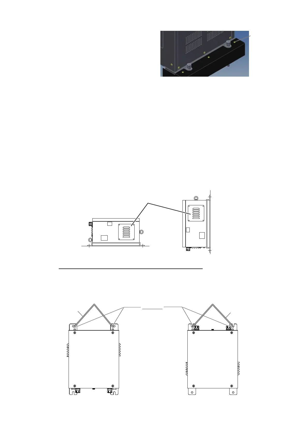
5. Place the anti-vibration device cov-
ers over the transceiver base, then
secure the covers to the anti-vibra-
tion devices using the M4x8 bolts
(supplied).
1.5 Power Supply Unit (FSV-252)
The power supply unit (FSV-252) for the transceiver unit can be mounted in two
manners, wall mount or deck mount. Fasten the FSV-252 in the mounting location
using four M10 bolts (local supply). The floor mount location should be a horizontal
plane. Adjust the air vents on the sides of the unit so the vent openings are facing
downwards.
Be sure the mounting location is strong enough to support the weight of the unit under
the continued vibration which is normally experienced on the ship.If necessary
reinforce the mounting location.
Note 1: Do not mount or place the FSV-252 on the transceiver unit.
Note 2: Make sure the FSV-252 is mounted with the cable entry points facing down.
Suspending the FSV-252 (when using a crane, etc.)
The FSV-252 weighs approximately 37.5 kg. The attached eye-bolts are used when
hanging the FSV-252. Only suspend the FSV-252 upside down when moving it, do not
install the FSV-252 upside down. Use the figure below for reference.
Unfasten the four screws and adjust
the air vents to point downwards.
Desktop/Deck mounted
Bulkhead mounted
Rope
Eyebolts
Default placement of eyebolts
Suspended upside down
Rope
When suspending the
unit upside down, place
the eyebolts at the
opposite side of the unit


 To Next Page