2. WIRING
2-2
2.2 Processor Unit
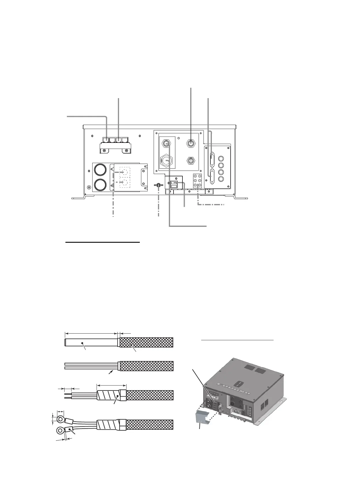
Referring to the figure below, connect external units to the processor unit via the front
panel of the processor unit. Make sure all cables are securely connected.
Power cable fabrication
1. Referring to the figure below, fabricate a DPYC-6 marine power cable (Maximum
length 5m, local supply.)
2. Remove the power terminal cover at the rear of the processor unit (See figure
below), then connect the DPYC-6 power cable. (Upper terminal is +, lower
terminal is -.)
3. Replace the power terminal cover to its original position.
4. Connect the processor unit earth to the ship’s earth with a ground wire (IV-8.sq,
local supply).
Transceiver unit
FSV-251
External monitor
(SXGA, UXGA, WUXGA)
DVI-D/D SLINK
(5 m or 10 m)
FR-FTPC-CY
(100 m or less)
19S1050, 3 m
10S2383, 3 m
IF Unit
FSV-8502
IF Unit
FSV-5802
PC speakers with amplifier
(5 W or less, local supply)
Sub controller
(FSV-853, option)
NMEA 0183 Equipment
Ground
wire IV-8sq.
To ship’s earth
12-24 VDC
DPYC-2.5
(Less than 5 m)
47
3
7
20
1
5.5
8 to 12
Power terminal cover
Power terminals
Outer sheath
Cable jacket
Cut and remove the outer sheath
Wrap with insulated tape
Crimp-on lugs (local supply)
All dimensions in millimeters


 To Next Page