63
<Model Basic Setting Procedure>
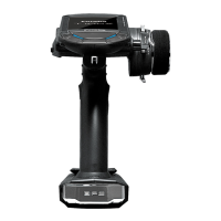
Receiver switch
Receiver battery
Charging port
In S.BUS
use
(8/SB)
S.BUS not
using it
(CH1-8)
(7/B)
Servos
●Always connect the necessary number of servos.
●The receiver channel assignment depends on the
model type. See the Servo connection by model
type tables.
R7008SB (output connector section)
(Receiver connectors)
●1~6: Output for conventional system CH1~6
●7/B: Output for conventional system CH7/Power supply
●8/SB: Output for conventional system CH8 or S.BUS port
●S.BUS2: S.BUS2 port
●Monitor LED
Telemetry sensor etc.
Receiver and servos connection diagram
Receiver and servos connection
Connect the receiver and servos in accordance with the connection diagram shown below. Always read
[Precautions when mounting the receiver and servos] and [Before using]. When mounting the receiver and
servos to the fuselage, connect the necessary points in accordance with the kit instruction manual.
●The Servo connection by model type tables are shown on the following pages.
Connect the servos to match the fuselage used.

 Loading...