Operators and Technicians Manual
© 2002 – 2007 FutureLogic, Incorporated. All Rights Reserved. MNL Page ii of 52 12/07/2007
MNL-000003 REV.N
List of Figures
Figure 2-1 Operator Indicators and Controls ...................................................................... 2
Figure 2-2 Load a Paper Stack ........................................................................................... 5
Figure 2-3 Feed Paper into Paper Loading Slot ................................................................... 5
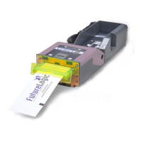
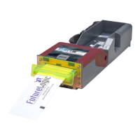
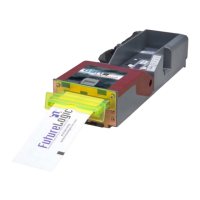
Figure 2-4 Sample Configuration Ticket ............................................................................. 6
Figure 2-5 Remove the Paper.............................................................................................. 7
Figure 2-6 Open the Lid ..................................................................................................... 7
Figure 2-7 Clear the Paper Jam.......................................................................................... 7
Figure 3-1 Ground Screw and Copper Grounding Clips Location........................................ 8
Figure 3-2 Disconnect the Coiled Cable Connector ............................................................. 9
Figure 3-3 Slide the Printer until It Locks........................................................................... 9
Figure 3-4 Remove the Paper............................................................................................ 10
Figure 3-5 Front Locking Bar ........................................................................................... 10
Figure 3-6 Push Release Bar ............................................................................................ 10
Figure 4-1 Front Bezel LED Control Port (All Models) ....................................................... 11
Figure 4-2 Netplex Interface Cable ................................................................................... 12
Figure 4-3 Netplex Firmware Upload Port ......................................................................... 14
Figure 4-4 Upload Cable Diagram .................................................................................... 14
Figure 4-5 Netplex Dip Switches – Top View ..................................................................... 15
Figure 4-6 RS232 Interface Cable, 12 Pin Coiled .............................................................. 16
Figure 4-7 RS232 Interface Cable, 14 Pin Coiled .............................................................. 18
Figure 4-8 RS232 Adapter Cable ...................................................................................... 19
Figure 4-9 RS232 Evaluation Cable.................................................................................. 20
Figure 4-10 RS232 Firmware Upload Port .......................................................................... 22
Figure 4-11 Upload Cable Diagram .................................................................................... 22
Figure 4-12 Dip Switches – Top View.................................................................................. 23
Figure B-1 Ticket Dimensional Specification..................................................................... 26