Section 50 00-02-1032
2020-12-08 - 3 -
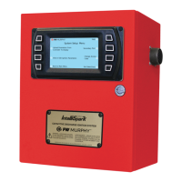
C5-1 Digital Input LED Indicators – Digital Inputs
Green LED:
On - Input active (DC+ or -)
Off - Input active (open)
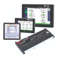
C5-1 Digital Output LED Indicators – Relay Outputs, FET DC+, FET DC-
Green LED:
On - Output on
Off - Output off
C5-1 Communication LED Indicators - RS232, RS485, CAN bus
RED LED:
Flash - Unit is transmitting data to device
Off - No communication active
GREEN LED:
Flash - Unit is receiving data
Off - No communication active
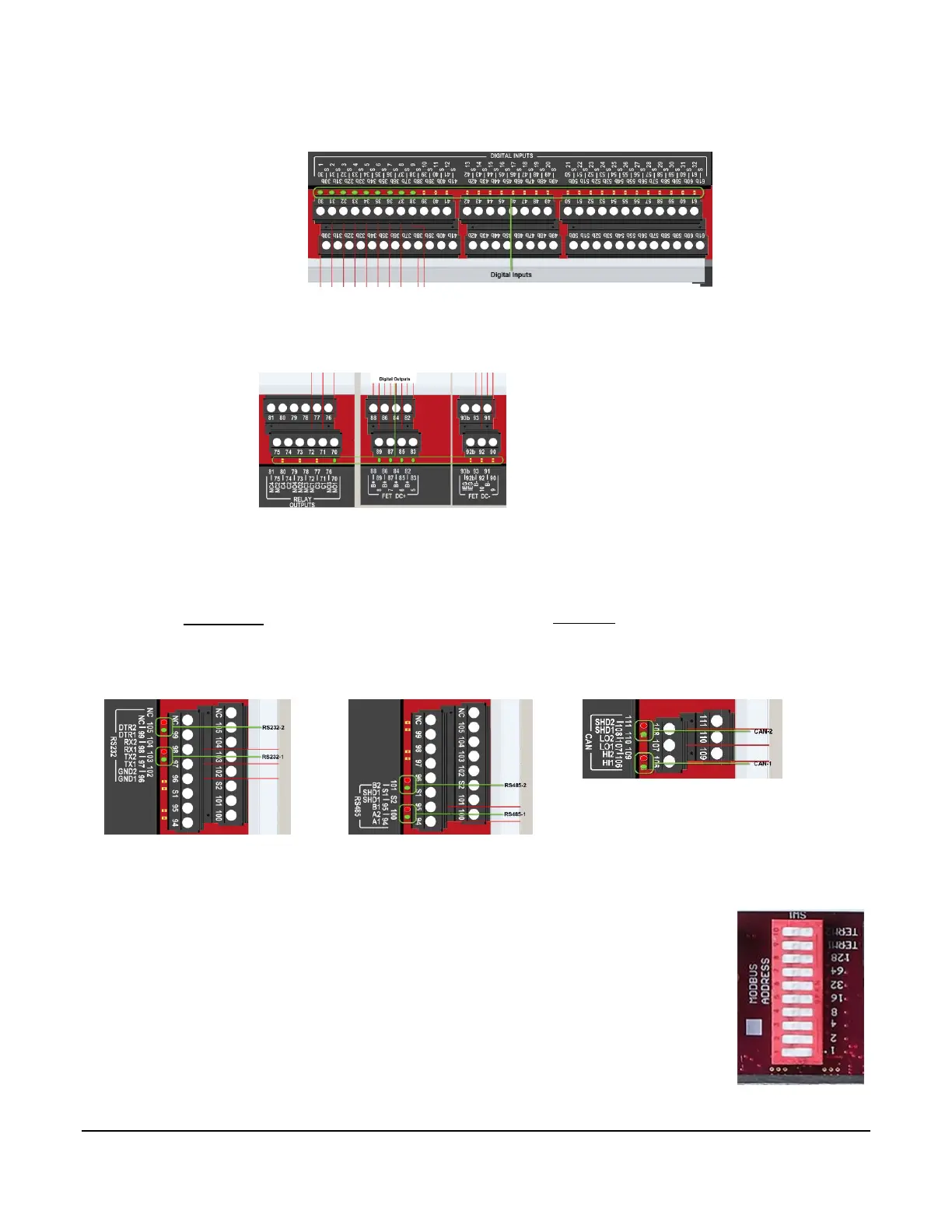
C5-1 DIP Switch Setting
Switch 1-8: Modbus Slave Address function for RS485-2 / RS232-2
Selectable 1-253
If set to address 0, RS485-2 and RS232-2 ports default to 9600 baud.
Set to address 1 to connect to the controller if settings are not known. This is the
default setting from the factory.
Switch 9: Set to ON to enable CAN1 line termination if C5-1 is at the end of the CAN bus
network.
Switch 10: Set to ON to enable CAN2 line termination if C5-1 is at the end of the CAN bus
network.
 Loading...