190-02692-00 Rev. A
Garmin G100 Pilot’s Guide for the Piper PA-32 Saratoga
56
FLIGHT INSTRUMENTS
SYSTEM
OVERVIEW
FLIGHT
INSTRUMENTS
EIS
AUDIO PANEL
& CNS
FLIGHT
MANAGEMENT
HAZARD
AVOIDANCE
AFCS
ADDITIONAL
FEATURES
APPENDICESINDEX
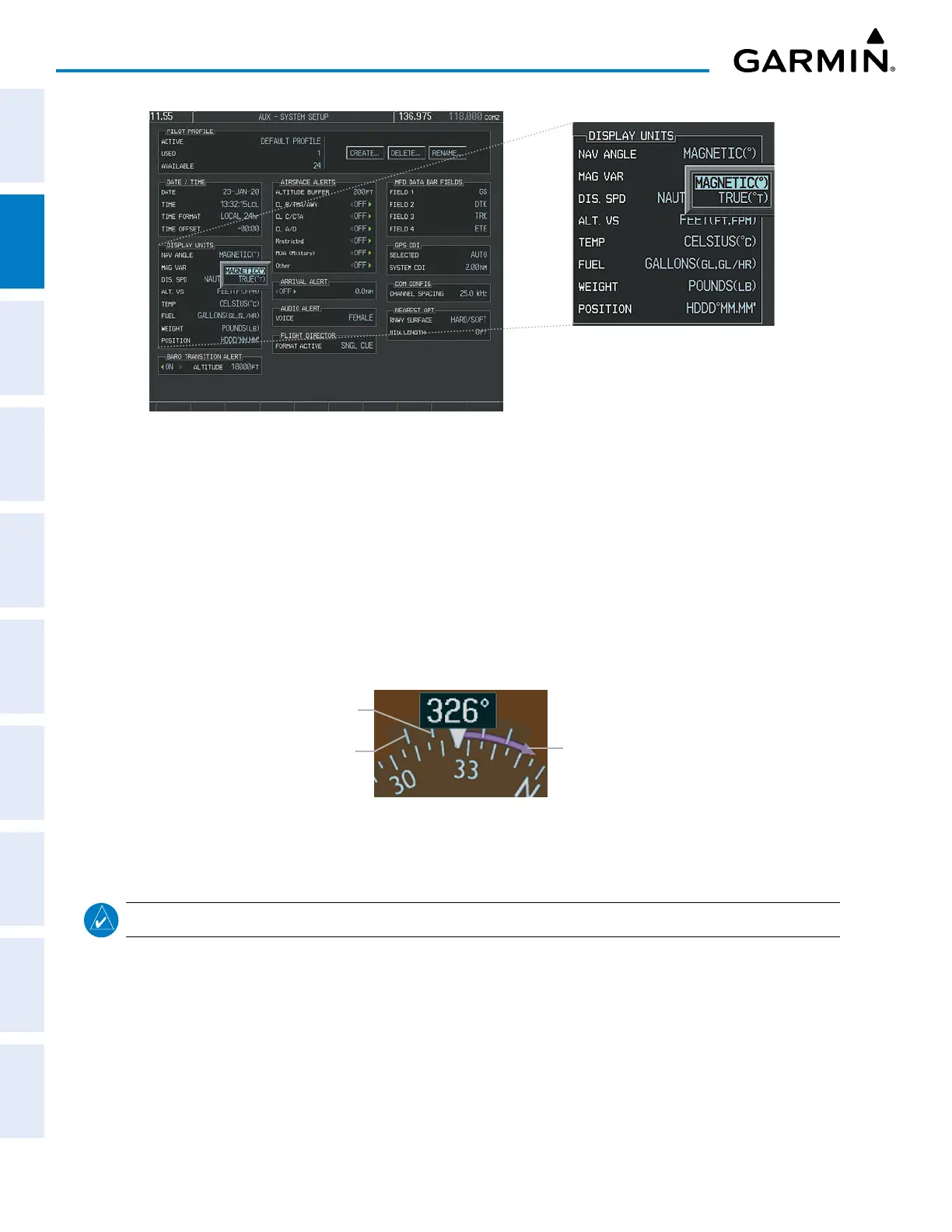
Figure 2-15 AUX – SYSTEM SETUP Page, Navigation Angle
Settings
TURN RATE INDICATOR
The Turn Rate Indicator is located directly above the rotating compass card. Tick marks to the left and
right of the lubber line denote half-standard and standard turn rates. A magenta Turn Rate Trend Vector
shows the current turn rate. The end of the trend vector gives the heading predicted in six seconds, based
on the present turn rate. A standard-rate turn is shown on the indicator by the trend vector stopping at the
standard turn rate tick mark, corresponding to a predicted heading of 18˚ from the current heading. At rates
greater than four deg/sec, an arrowhead appears at the end of the magenta trend vector and the prediction is
no longer valid.
Arrow Shown
for Turn Rate
> 4 deg/sec
Half-standard
Turn Rate
Standard
Turn Rate
Figure 2-16 Turn Rate Indicator and Trend Vector
BEARING POINTERS AND INFORMATION WINDOWS
NOTE: When the Arc HSI is displayed, the bearing information windows and pointers are disabled.
Two bearing pointers and associated information can be displayed on the HSI for NAV and GPS sources
by pressing the PFD Softkey then a BRG or DME Softkey. The bearing pointers are cyan and are single-line
(BRG1) or double-line (BRG2). A pointer symbol is shown in the information window(s) to indicate the
navigation source. The bearing pointers never override the CDI and are visually separated from the CDI by a
white ring. Bearing pointers may be selected but not necessarily visible due to data unavailability.


 To Next Page