External ducts
If additional duct work is added externally to the Rittal
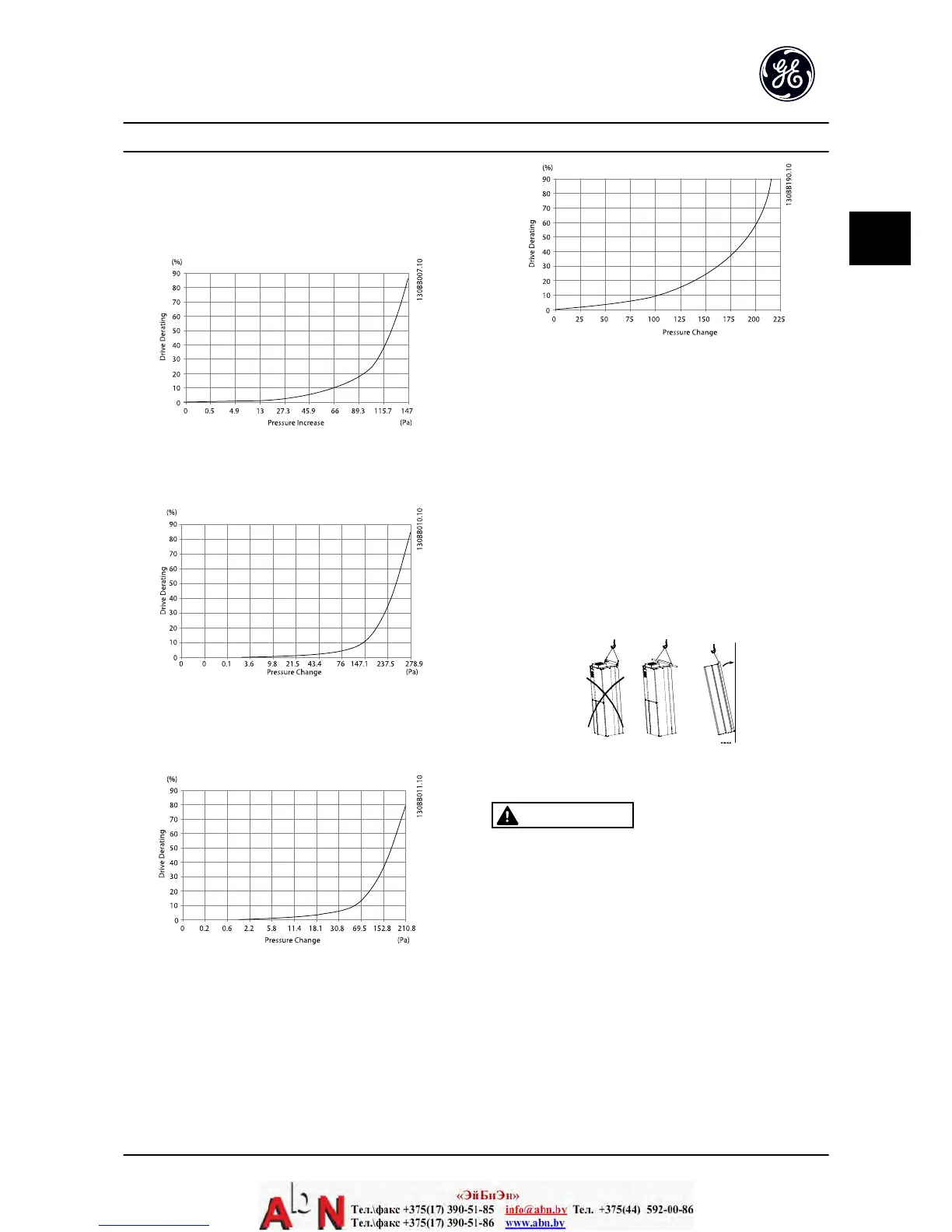
cabinet, the pressure drop in the ducting must be
calculated. Use the charts below to derate the adjustable
frequency drive according to the pressure drop.
Figure 2.2 Unit Size 4X Derating vs. Pressure Change
Drive air flow: 450 cfm (765 m
3
/h)
Figure 2.3 Unit Size 5X Derating vs. Pressure Change (Small Fan),
350 hp @ 460 V and 500–550 hp @ 690 V
Drive air flow: 650 cfm (1105 m
3
/h)
Figure 2.4 Unit Size 5X Derating vs. Pressure Change (Large Fan)
Drive air flow: 850 cfm (1445 m
3
/h)
Figure 2.5 Unit Size 61, 62, 63 and 64 Derating vs. Pressure
Change
Drive air flow: 580 cfm (985 m
3
/h)
2.3.3 Lifting
•
Check the weight of the unit to determine a safe
lifting method
•
Ensure that the lifting device is suitable for the
task
•
If necessary, plan for a hoist, crane, or forklift with
the appropriate rating to move the unit
•
For lifting, use hoist rings on the unit, when
provided
Figure 2.6 Recommended Lifting Method, 4X and 5X Unit Sizes.
WARNING
The lifting bar must be able to handle the weight of the
adjustable frequency drive. See Mechanical Dimensions for
the weight of the different unit sizes. Maximum diameter
for bar is 1 in [2.5 cm]. The angle from the top of the
adjustable frequency drive to the lifting cable should be
60° or greater.
2.3.4 Mounting
•
Mount the unit vertically
•
The adjustable frequency drive allows side by
side installation
•
Ensure that the strength of the mounting location
will support the unit weight
Installation AF-600 FP Design and Installation Guide
DET-768A 2-3
2

 Loading...


