Figure 9.3
Warn. LED Alarm LED
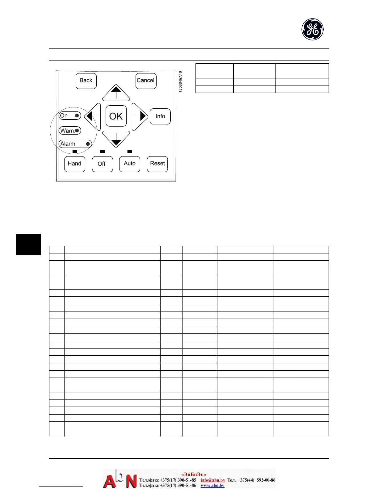
Warning On Off
Alarm Off On (Flashing)
Trip Lock On On (Flashing)
Table 9.1
9.4 Warning and Alarm Definitions
Table 9.2 defines whether a warning is issued before an alarm, and whether the alarm trips the unit or trip locks the unit.
No. Description Warning Alarm/Trip Alarm/Trip Lock Parameter Reference
1 10 Volts low X
2Live zero error (X) (X) AN-01 Live Zero Timeout
Function
4Mains phase loss (X) (X) (X) SP-12 Function at Line
Imbalance
5 DC link voltage high X
6 DC link voltage low X
7DC overvoltage X X
8 DC undervoltage X X
9 Inverter overloaded X X
10 Motor electronic overload (X) (X) F-10 Electronic Overload
11 Motor thermistor over temperature (X) (X) F-10 Electronic Overload
12 Torque limit X X
13 Overcurrent X X X
14 Ground fault X X X
15 Hardware mismatch X X
16 Short-circuit X X
17 Control word timeout (X) (X) O-04 Control Word
Timeout Function
18 Start Failed
23 Internal Fan Fault X
24 External Fan Fault X SP-53 Fan Monitor
29 Drive over temperature X X X
30 Motor phase U missing (X) (X) (X) H-78 Missing Motor Phase
Function
Warnings and Alarms AF-600 FP Design and Installation Guide
9-2 DET-768A
9

 Loading...


