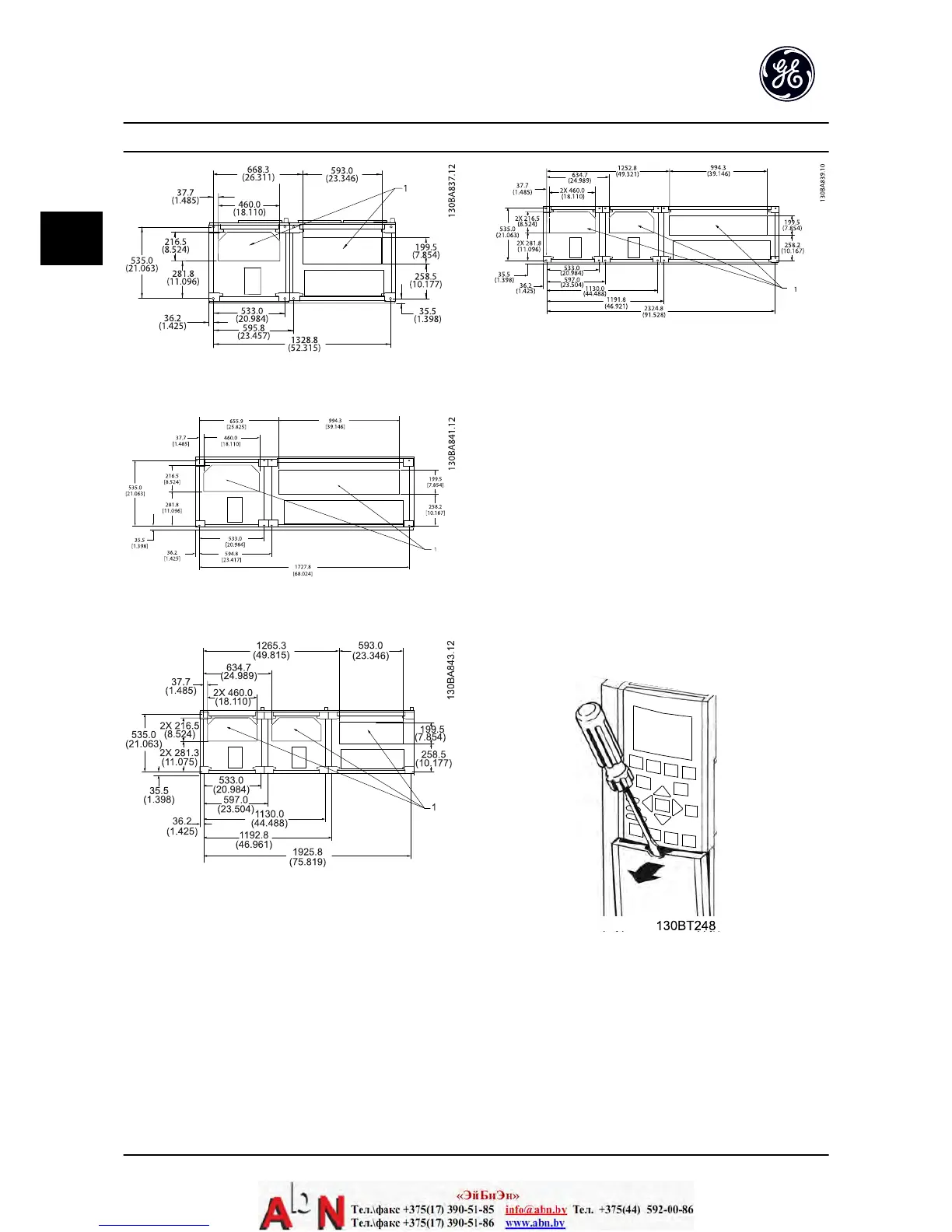
Figure 2.22 Unit Size 61
Figure 2.23 Unit Size 62
Figure 2.24 Unit Size 63
Figure 2.25 Unit Size 64
2.5.8 Control Wiring
•
Isolate control wiring from high power
components in the adjustable frequency drive.
•
If the adjustable frequency drive is connected to
a thermistor, for PELV isolation, optional
thermistor control wiring must be reinforced/
double insulated. A 24 V DC supply voltage is
recommended.
2.5.8.1 Access
•
Remove access cover plate with a screw driver.
See Figure 2.26.
•
Or remove front cover by loosening attaching
screws. See Figure 2.27.
Figure 2.26 Control Wiring Access for IP20/Open chassis
enclosures
Installation AF-600 FP Design and Installation Guide
2-12 DET-768A
2

 Loading...


