•
EN 61000-4-5 (IEC 61000-4-5): Surge transients:
Simulation of transients brought about, e.g., by
lightning that strikes near installations.
•
EN 61000-4-6 (IEC 61000-4-6): RF Common mode:
Simulation of the effect from radio-transmission
equipment joined by connection cables.
See Table 7.4.
Voltage range: 200–240 V, 380–480 V
Basic standard Electrical
interference
IEC 61000-4-4
Surge
IEC 61000-4-5
ESD
IEC
61000-4-2
Radiated electromagnetic
field
IEC 61000-4-3
RF common
mode voltage
IEC 61000-4-6
Acceptance criterion B B B A A
Line
4 kV CM
2 kV/2 Ω DM
4 kV/12 Ω CM
——
10 V
RMS
Motor
4 kV CM
4 kV/2 Ω
1)
——
10 V
RMS
Brake 4 kV CM
4 kV/2 Ω
1)
——
10 V
RMS
Load sharing 4 kV CM
4 kV/2 Ω
1)
——
10 V
RMS
Control wires
2 kV CM
2 kV/2 Ω
1)
——
10 V
RMS
Standard bus 2 kV CM
2 kV/2 Ω
1)
——
10 V
RMS
Relay wires 2 kV CM
2 kV/2 Ω
1)
——
10 V
RMS
Application and Network
options
2 kV CM
2 kV/2 Ω
1)
——
10 V
RMS
Keypad cable
2 kV CM
2 kV/2 Ω
1)
——
10 V
RMS
External 24 V DC
2 kV CM
0.5 kV/2 Ω DM
1 kV/12 Ω CM
——
10 V
RMS
Enclosure
——
8 kV AD
6 kV CD
10 V/m —
AD: Air Discharge
CD: Contact Discharge
CM: Common mode
DM: Differential mode
1. Injection on cable shield.
Table 7.5 EMC Immunity Form
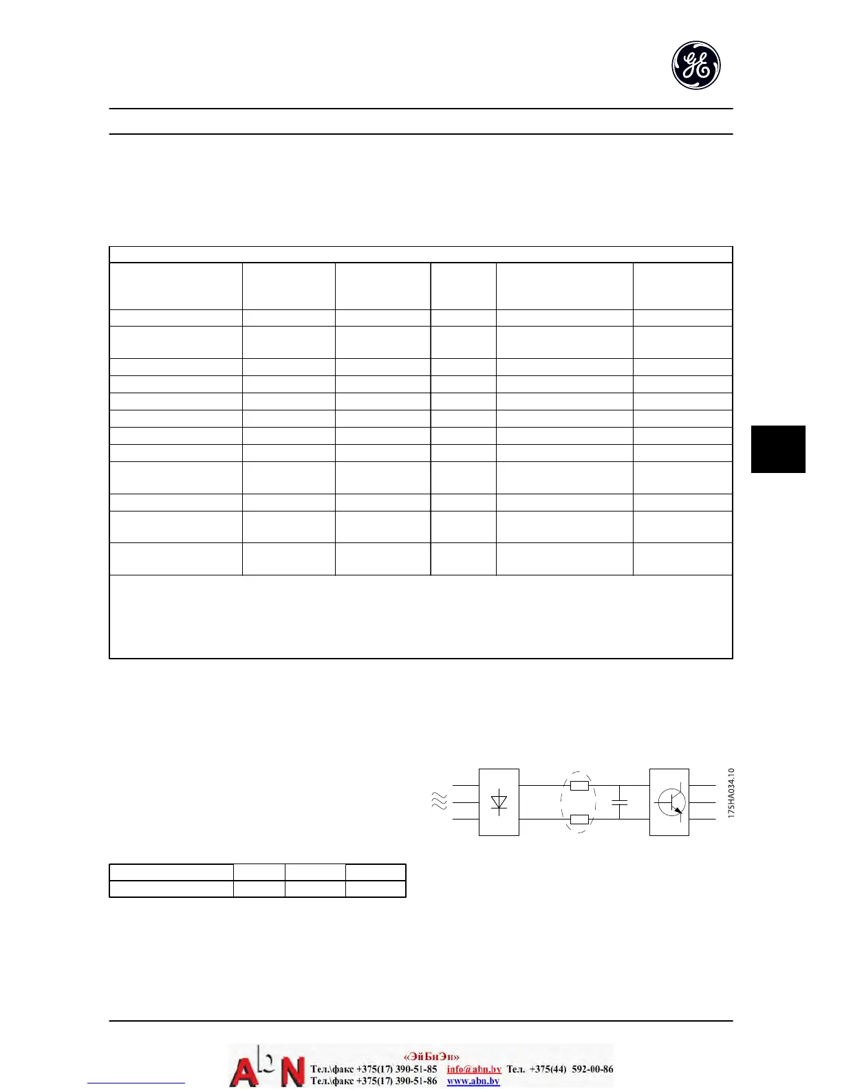
7.3 General Aspects of Harmonics Emission
An adjustable frequency drive takes up a non-sinusoidal
current from the line power, which increases the input
current I
RMS
. A non-sinusoidal current is transformed by
means of a Fourier analysis and split up into sine-wave
currents with different frequencies, i.e., different harmonic
currents I
N
with 50 Hz as the basic frequency:
Harmonic currents I
1
I
5
I
7
Hz 50 Hz 250 Hz 350 Hz
Table 7.6
The harmonics do not affect the power consumption
directly but increase the heat losses in the installation
(transformer, cables). Consequently, in plants with a high
percentage of rectifier load, maintain harmonic currents at
a low level to prevent an overload of the transformer and
high temperature in the cables.
Figure 7.2
Installation Consideration AF-600 FP Design and Installation Guide
DET-768A 7-5
7

 Loading...


