CAUTION
Thermistors must use reinforced or double insulation to
meet PELV insulation requirements.
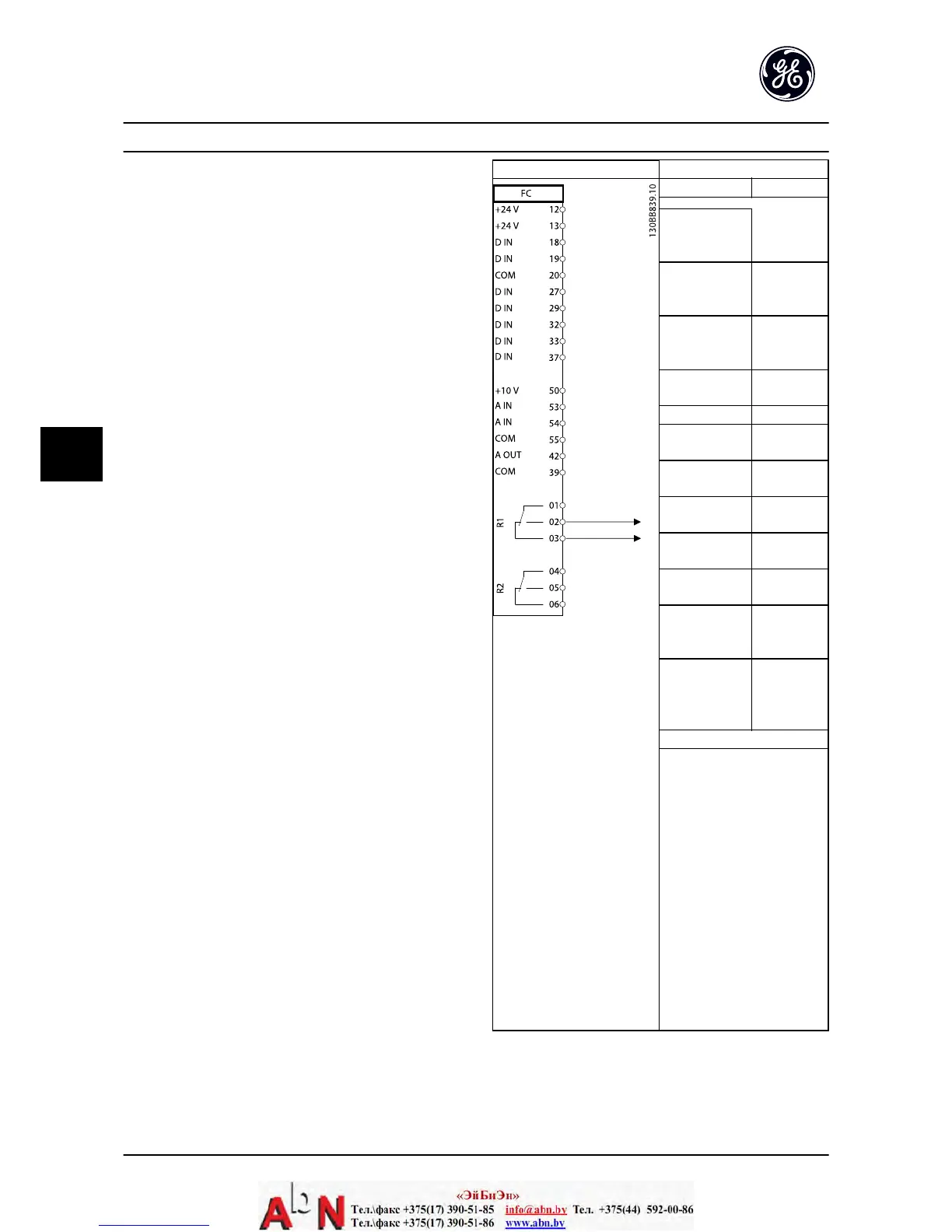
Parameters
Function Setting
H-20 Motor
Feedback Loss
Function [1] Warning
H-21 Motor
Feedback Speed
Error
100 RPM
H-22 Motor
Feedback Loss
Timeout
5 sec
LC-00 Logic
Controller Mode
[1] On
LC-01 Start Event [19] Warning
LC-02 Stop Event [44] Reset
key
LC-10 Comparato
r Operand
[21] Warning
no.
LC-11 Comparato
r Operator
[1] ≈*
LC-12 Comparato
r Value
90
LC-51 Logic
Controller Event
[22]
Comparator 0
LC-52 Logic
Controller Action
[32] Set
digital out A
low
E-24 Function
Relay
[80] Logic
Controller
digital output
A
* = Default Value
Notes/comments:
If the limit in the feedback
monitor is exceeded, Warning
90 will be issued. The monitors
Warning 90 and in the case
that Warning 90 becomes TRUE,
then Relay 1 is triggered.
External equipment may then
indicate that service may be
required. If the feedback error
goes below the limit again
within 5 sec., then the drive
continues and the warning
disappears. But Relay 1 will still
be triggered until [Reset] on
the keypad.
Table 6.9 Using Logic Controller to Set a Relay
Application Set-up Examples AF-600 FP Design and Installation Guide
6-4 DET-768A
6

 Loading...


