Illustration of the flow path
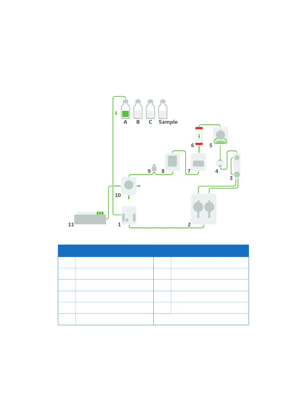
The illustration below shows the flow path for a standard configured ÄKTA go instrument
with an optional fraction collector connected. The individual instrument modules are
presented in the table below. The system configuration is defined by the user in the
UNICORN Administration module.
DescriptionPartDescriptionPart
UV monitor U9-L7Inlet valve K91
Conductivity monitor C98Pump P9-S2
Flow restrictor FR-9029Pressure monitor R93
Outlet valve V9-Os10Mixer4
Fraction collector F9-R11Injection valve V9-J5
Column6
62 ÄKTA go Operating Instructions 29360951 AC
5 Prepare the system for a run
5.1 Prepare the flow paths

 Loading...


