AC.24.013
1
4
2
3
13
11
7
6
9
12
8
5
14
10
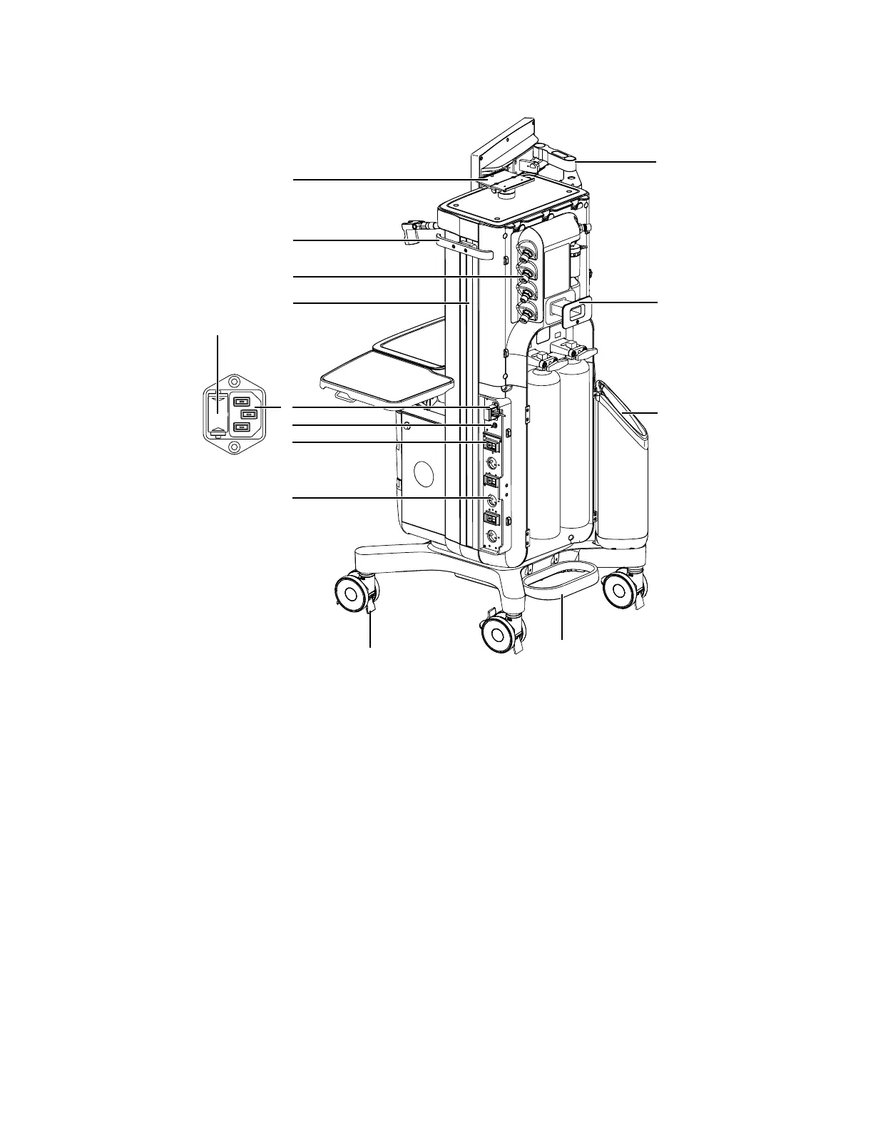
1. Display arm 8. Equipotential stud
2. Cable hook 9. Mains inlet
3. Third cylinder mount 10. Mains power fuses (inside)
4. Cylinder guard 11. Right dovetail
5. Caster guard 12. Pipeline connections
6. Electrical outlets 13. Side rail
7. Outlet circuit breakers 14. Top shelf monitor mount
Figure 2-2 • Rear view (Left)
2 System controls and menus
2076152-001 2-3
 Loading...