CB Watch 3 User Manual v6.3 - May 2019 Page 4 of 100
Illustrations
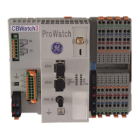
Figure 1 – CBW3 Modules .......................................................................................................................... 9
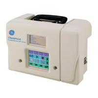
Figure 2 – examples of sensors used ......................................................................................................... 9
Figure 3 – Network card configuration step 1 ......................................................................................... 10
Figure 4 – Network card configuration step 2 ......................................................................................... 10
Figure 5 – Network card configuration step 3 ......................................................................................... 11
Figure 6 – CBW3 network connections .................................................................................................... 11
Figure 7 – Connection to the CBW3 ......................................................................................................... 12
Figure 8 – Connection warning ................................................................................................................ 12
Figure 9 – Connection advanced page ..................................................................................................... 13
Figure 10 – HMI CBW3 log in ................................................................................................................... 13
Figure 11 – HMI language selection ......................................................................................................... 14
Figure 12 – HMI secondary toolbar for System section ........................................................................... 15
Figure 13 – CBW3 product information ................................................................................................... 15
Figure 14 – Set button example ............................................................................................................... 15
Figure 15 – Changing password ............................................................................................................... 16
Figure 16 – Number of opening/closing operation.................................................................................. 17
Figure 17 – Initial setting of number of operations ................................................................................. 18
Figure 18 – Setting operation counter alarms ......................................................................................... 18
Figure 19 – Auxiliary contact status ......................................................................................................... 18
Figure 20 – Pole discrepancy timeout threshold ..................................................................................... 18
Figure 21 – Pole discrepancy alarm ......................................................................................................... 19
Figure 22 – Setting operation counter alarms ......................................................................................... 19
Figure 23 – Auxiliary contact timing ........................................................................................................ 20
Figure 24 – Auxiliary contact opening and closing graphs ....................................................................... 20
Figure 25 – Auxiliary contacts switching threshold ................................................................................. 20
Figure 26 – Monitoring the auxiliary contacts ......................................................................................... 20
Figure 27 – Operating time measurement .............................................................................................. 21
Figure 28 – Last operation measurements .............................................................................................. 22
Figure 29 – Operating time discordances ................................................................................................ 23
Figure 30 – Entry of key distances ........................................................................................................... 23
Figure 31 – Separation and touching speed ............................................................................................ 24
Figure 32 – Operation timing alarms thresholds ..................................................................................... 24
Figure 33 – Alarms related to operation timing ...................................................................................... 25
Figure 34 – Entry of distances .................................................................................................................. 26
Figure 35 – Operation graphs for opening ............................................................................................... 27
Figure 36 – Operation graph for closing .................................................................................................. 27
Figure 37 – Monitoring the auxiliary contacts ......................................................................................... 28
Figure 38 – Monitoring the auxiliary contacts ......................................................................................... 28
Figure 39 – Monitoring the overtravel ..................................................................................................... 29
Figure 40 – Displaying overtravel ............................................................................................................. 29
Figure 41 – Overtravel threshold ............................................................................................................. 30
Figure 42 – Overtravel alarm ................................................................................................................... 30
Figure 43 – Timing compensation ............................................................................................................ 31
Figure 44 – Two examples of operating time temperature compensation values .................................. 32
Figure 45 – Example of closing operating time changes with voltage changes ....................................... 32
 Loading...