CB Watch 3 User Manual v6.3 - May 2019 Page 62 of 100
Setting Alarms
Notice: It is the customer’s responsibility to decide whether to set alarms or not and to
decide what thresholds to set alarms at, as this will depend on the customer’s
operational priorities and risk philosophy. However, here are some guidelines that may
prove helpful in deciding what threshold values to use:
Alarm summary
This table summarises all the alarms that can be set for control circuit monitoring:
Figure 97 – Control circuit monitoring alarms
Threshold values
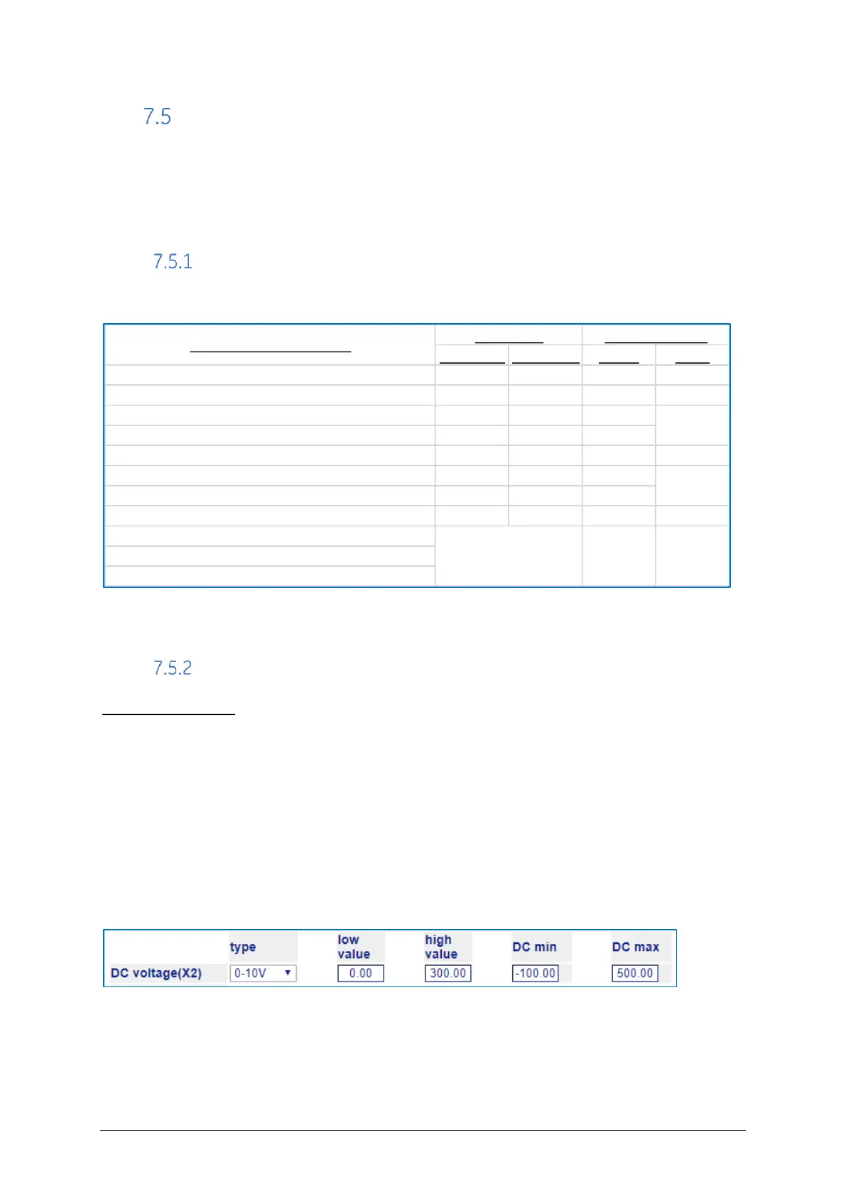
DC Voltage Supply
This depends on what acceptable level has been set as a policy or what minimum
voltage is required by the coils. Normally, low voltage tests are run during the CB FAT and
the lowest tested value could be used as the minimum alarm level. High level alarm is
much less of a concern and can be effectively de-activated by using a very high
threshold like 500V.
If this function is not being monitored and no sensor is present, then the values should be
set as such to avoid any erroneous alarm:
HMI: Settings / Analogue channels
Figure 98 – DC voltage default settings
Min Alarm Max Alarm Digital Relay
Coil circuit DC voltage source 1 Yes Yes Yes Yes
Coil circuit DC voltage source 2 Yes Yes Yes Yes
Mean coil current - Open 1, per pole No Yes Yes
Mean coil current - Open 2, per pole No Yes Yes
Mean coil current - Close, per pole No Yes Yes Yes
Coil actuation charge - Open 1, per pole Yes Yes Yes
Coil actuation charge - Open 2, per pole Yes Yes Yes
Coil actuation charge - Close, per pole Yes Yes Yes Yes
Coil continuity - Open 1, per pole
Coil continuity - Open 2, per pole
Coil continuity - Close, per pole
 Loading...