Chapter 2: Installation
Concord 4 Installation Manual 19
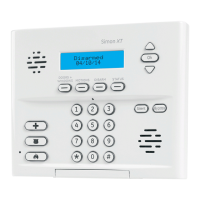
Figure 11: Connecting exterior sirens
Panel terminals
Red
Black
OUT1 GND
Output 2
Onboard output 2 (OUT 2—terminal 10) is an open-collector (switched path-to-
ground), programmable output that can handle a maximum of 300 mA current sink
and up to 14 VDC. The default setting (01710) activates the output for status and
alarm tones, allowing for a piezo siren connection without changing the output
configuration number. This output is typically used for interior siren applications. (For
more information on output configuration numbers, see “Onboard options menu” on
page 75.)
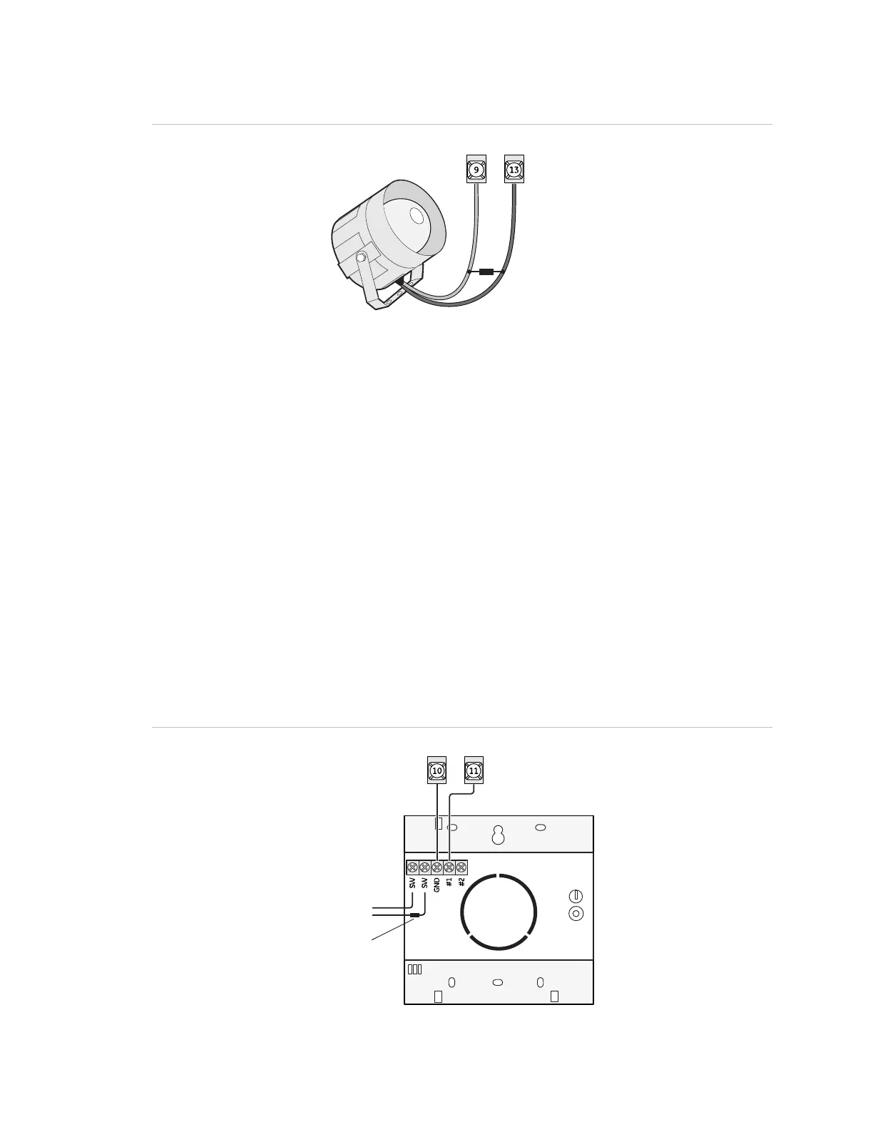
Hardwired interior siren (13-949)
This siren has two inputs, steady (#1) and warble (#2). Use the steady (#1) terminal for
Concord 4 panels. The siren also includes a cover tamper switch that can be
connected to a hardwired zone input on the panel, SnapCard or SuperBus 2000
hardwired input module. Connect the siren to the panel/zone input terminals as
shown in Figure 12 below.
Figure 12: Connecting an interior siren
OUT2 +12V
To zone input
2 kohm resistor

 Loading...