FP1500 Installation, Configuration and Commissioning Manual 10
3 INSTALLATION OF THE SYSTEM
This chapter describes the installation process step by step, from fixing the fire panel to
the wall to connecting each of the possible components of the system.
Follow each of the listed procedures carefully.
3.1 Installation tools
For installation:
A flat screwdriver for connectors and a Phillips screwdriver for the star-headed screws of
the front casing, wire-stripping pliers and, multi-meter (tester) is required.
For fixing to the wall:
Appropriate drill bits, plugs and screws for the type and thickness of the wall where the
fire panel is to be mounted is needed
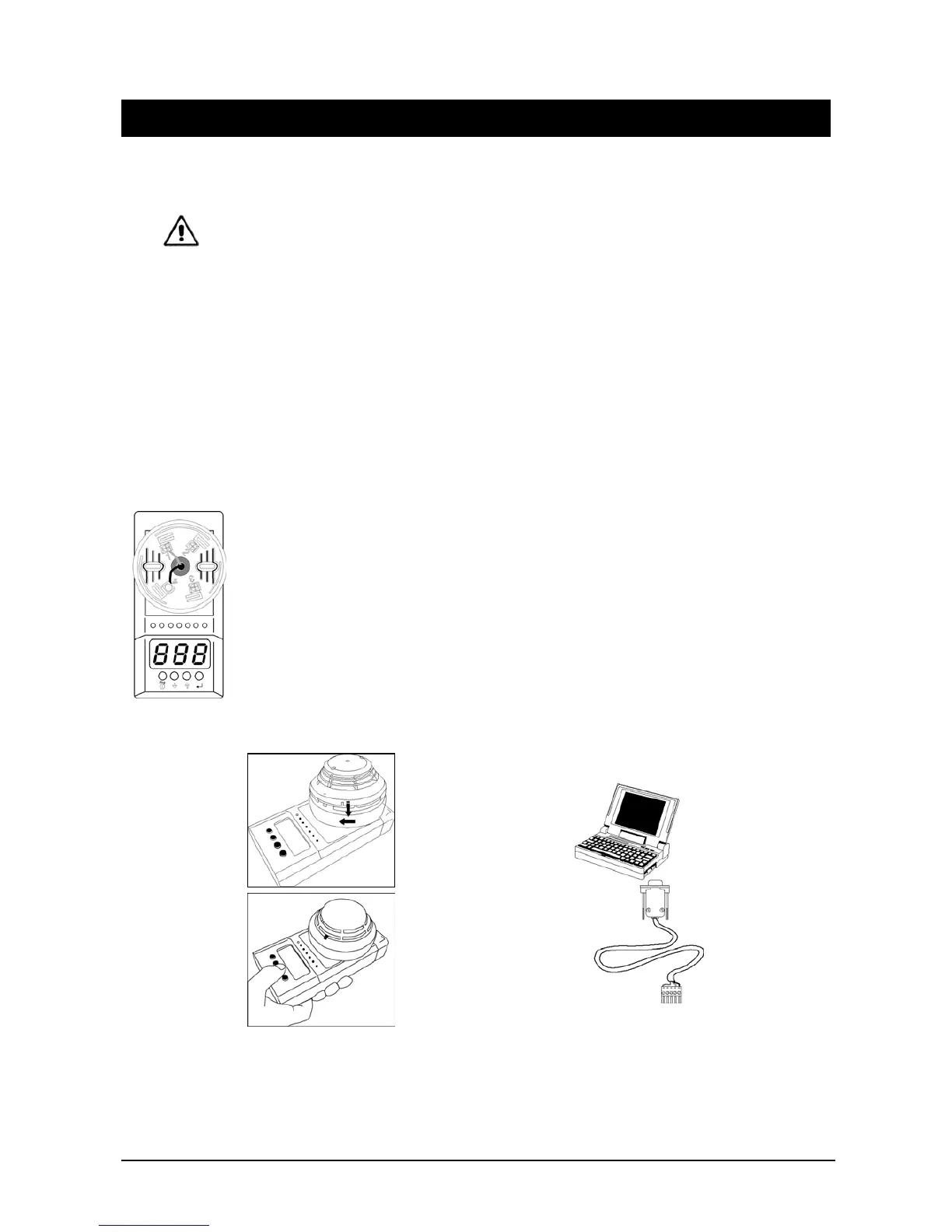
For configuring FP1500 panels and analogue sensors:
The PG700 Sensor Programmer is a portable unit for assigning addresses to 1500 Series
sensors. This unit has two operating modes:
Mode 1: Permits viewing the address of the detector by inserting it into the socket and
modifying it.
Mode 2: Permits viewing the analogue value of the detector.
The KSP701 is an optional serial cable for loading the configuration using the
configuration software. For running the software a PC with Windows 98 or later is also
required.
Figure 5. Configuration Tools