FP1500 Installation, Configuration and Commissioning Manual 18
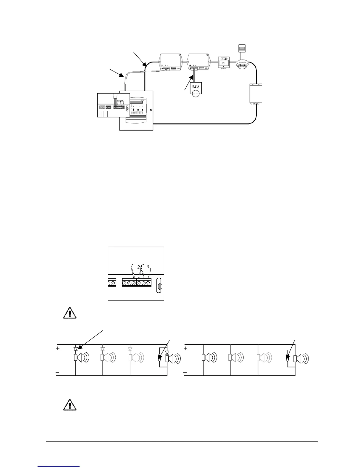
External power supply
24 V power supply line
from the fire panel
Output auxiliary 24 VDC
Figure 11. Additional power supply
3.5.6 Connecting sounders
The FP1500 has 2 sounder outputs internally, identified as SND1 and SND2. On each of
these outputs, supervised sirens may be connected with a total consumption of 300 mA.
The installation and connection procedures are as follows:
1. Install the cable connecting any polarized siren (or with a corresponding diode) as
required (without exceeding 300 mA).
2. Place a 4K7 / ¼ W end-of-line resistance in last siren.
3. Connect the circuit to the control unit through the terminals on the main board
identified as SND1+ and SND1-.
Figure 12. Connection of supervised sirens to the base of the main board
Use polarized sounders or install a diode to prevent them from triggering when on standby.
Aritech sirens are polarized (no diode is required)
Connection of non-polarized sirens Connection of polarized sirens
DIODE
END OF LINE RESISTOR END OF LINE RESISTOR