FP1500 Installation, Configuration and Commissioning Manual 5
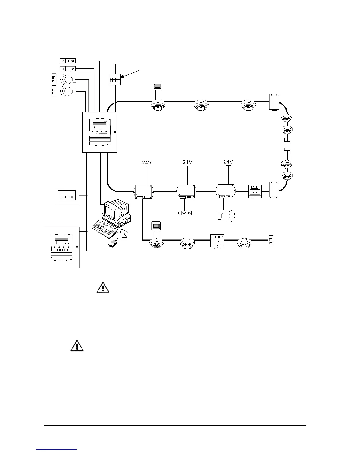
Figure 2. Basic diagram of the FP1500 analogue addressable fire detection system
Applicable local authority laws and requirements must be respected where
modules and detectors are used on loops.
1.4 Safety precautions and warnings
It is important to bear the following warnings in mind to avoid possible mishaps or
accidents.
• The fire panel is quite heavy once the batteries are installed. Use resistant fastening
elements.
• The system must be installed as far away from other cables as possible to minimize
the risk of external interference. The use of stranded, shielded cable is
recommended.
• Cable with a minimum section of 1.5 mm² and 250 VAC cable is recommended. The
cable length must not be longer than 2 km.
• The fire panel must be connected to an external bipolar magneto-thermal switch.
• Do not work on any connections without first disconnecting the external magneto-
thermal switch. Do not use the mains fuse to cut the power supply.
BIPOLAR
MAGNETO-THERMAL
SWITCH
RELAY OUTPUT
SUPERVISED
SOUNDERS
REMOTE
INDICATOR
ANALOGUE ADDRESSABLE SENSORS:
IONISATION OPTICAL HEAT
DI1552 DP1551 DT1553
ISOLATOR
KAL470
FP1500
1 or 2 LOOPS
RS232
REPEATER
PANEL
PC
CONVENTIONAL
MODULE