FP1500 Installation, Configuration and Commissioning Manual 7
2 THE FP1500 ANALOGUE FIRE PANEL
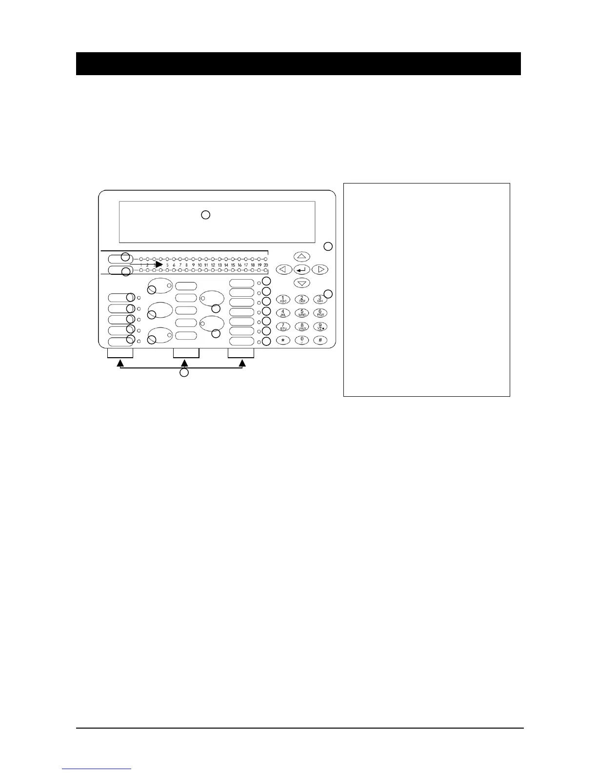
2.1 Description of the control panel
This section provides a visual diagram of the control panel keyboard and of the main
board connectors in order to facilitate the identification of each of the components of the
fire panel.
Figure 3. FP1500 Analogue addressable fire panels
1
2
5
6
7
8
9
10
11
12
13
14
15
16
17
18
19
20
21
22
23
24
4
1. Liquid crystal display
2. Alarm/zone LED
3. Zone numbering
4. Fault/Disable/Test zone LED
5. Service LED
6. General alarm LED
7. General fault LED
8. General disable LED
9. General test LED
10. Triggering of sirens (LED and key)
11. Silence sounders (LED and key)
12. Reset
13. Silence Buzzer (LED and key)
14. Evacuation (LED and key)
15. Multi-language inserts
16. Out-of-service LED
17. Power supply fault LED
18. System fault LED
19. Sounder fault/disabled LED
20. Delay mode LED
21. Relay disable LED
22. Earth fault LED
23. Keypad with Enter key
24. Alphanumeric keyboard