FP1500 Installation, Configuration and Commissioning Manual 14
3.5.2 Connections on the main electronic board
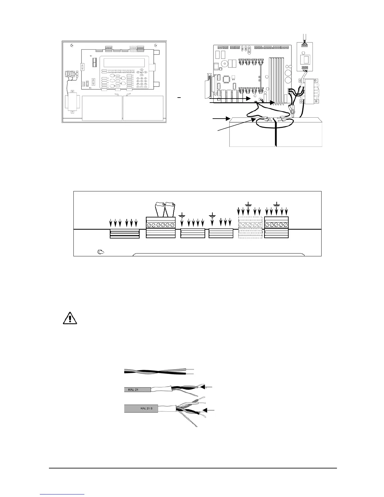
Figure 9. FP1500 main board connectors
3.5.3 Connecting a loop
The loop structure is a closed (Class A) circuit. All the elements are connected to two
wires that exit from the fire panel and return back to the fire panel again.
The cable used in the sensor loop installation has to be at least stranded with a 1.5 mm²
diameter. It should be shielded to avoid external interference. See section 7 Technical
specifications for full cable recommendations.
The maximum length of the loop is 2 km. The resistance of the loop cable must be less
than 44 Ohm and the maximum capacitance of the line must be less than 500 nF.
• Connect each detector and module to the loop along the cable run (See sections
3.5.4 and 3.5.7). Once the loop has been installed, connect it to the fire panel:
• Connect the loop to the terminal corresponding to loop 1 or 2.
NA
NC
C
RELAY2 RELAY1
NA
NC
C
24VDC AUX SND 2 SND 1
+ 1 + 1 + 1
RS485
B
A
B
A
RS232
RTS
RXB
TXA
LOOP 1
O+
O-
R+