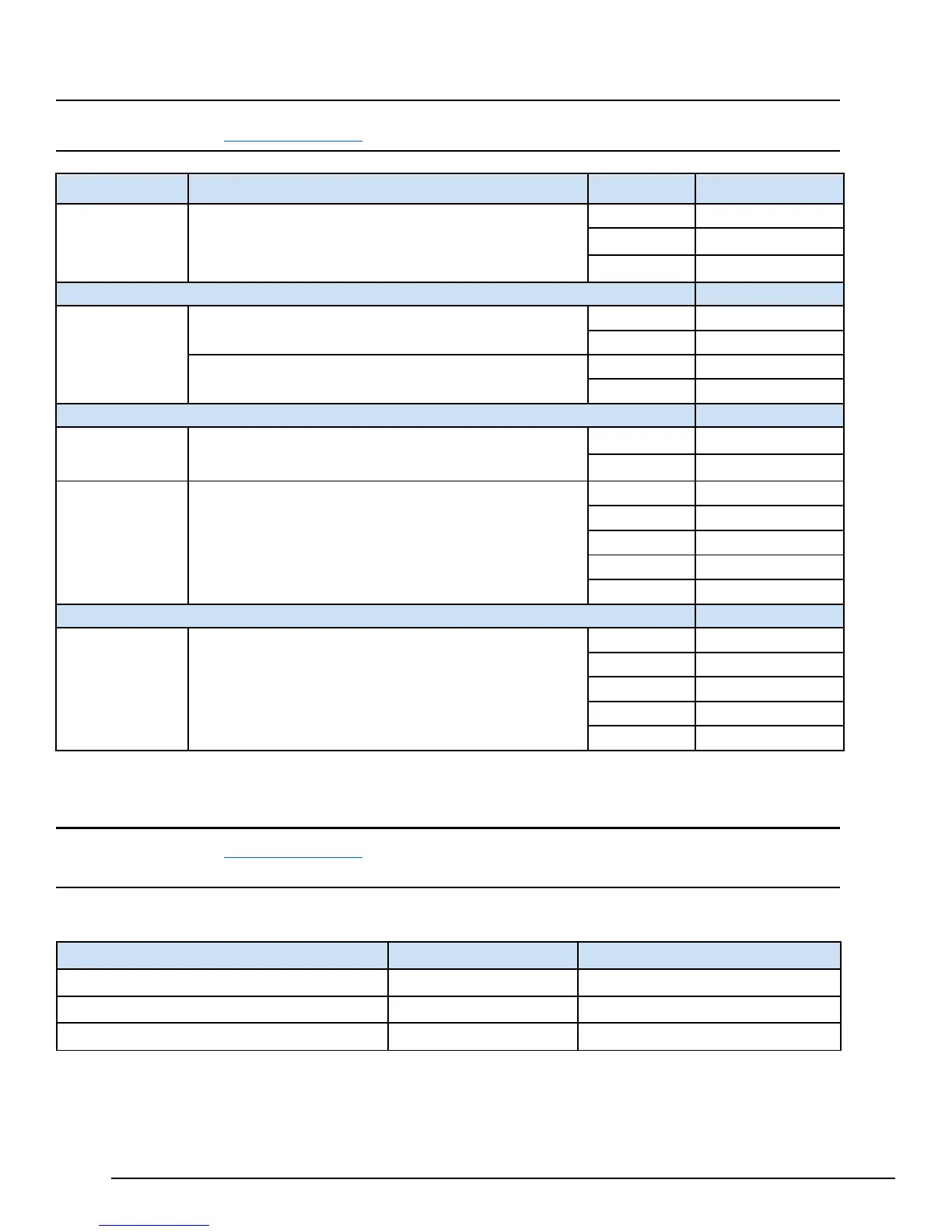
2.1.1.5 Pin Definitions
Note Refer to the section MFA Interface Details
for a figure that displays the physical locations of each pin.
Connector
Function
Pin Number
Description
PWR
Power connector
(9 to 30 V dc)
1 Ground
2
Negative Voltage
3
Positive Voltage
IO
Normally Open relay contact output, 30 V dc, 1 A resistive load
2 K1-B
+24 V Opto-coupled Input, 10 mA
3 IN+
CAN bus
Serial
1
CAN_H
2
CAN_L
RS-485
Serial
3 Ground
4 A /RX
5 B /CTS
6 Y /TX
RS-232
Serial
2 RX
3 GND
4 RTS
5 CTS
2.1.1.6 Network Configuration
Note Refer to the section
MFA Interface Details
for a figure that displays the physical locations of the LAN and WAN
Ethernet interfaces.
The default WAN and LAN IP addresses of the Mini Field Agent are displayed in the following table.
Item
WAN
LAN
IP Address Obtain using DHCP 192.168.1.100
Subnet Mask Obtain using DHCP 255.255.255.0
Gateway Obtain using DHCP Not set
WAN connects to the uppermost RJ-45 connector. LAN connects to the three lower RJ-45 connectors and they are switched
internally.