2 Installation
10
Monitor UV-900 User Manual 18-1120-05 Edition AF
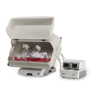
2.3 Installing the flow cell
2.3.1 Fixing the flow cell
Handle the optical fibers with care,
do not bend excessively.
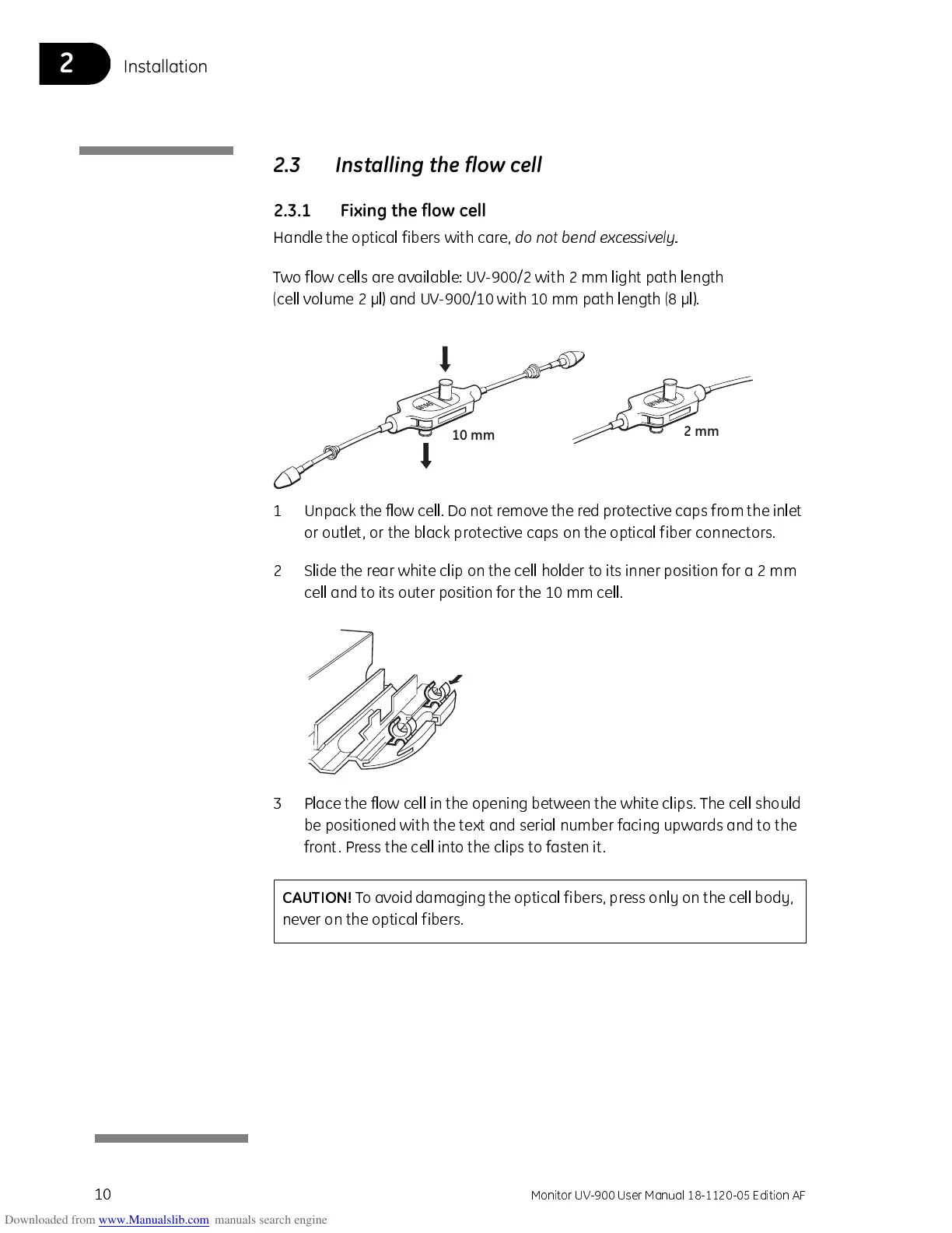
Two flow cells are available: UV-900/2 with 2 mm light path length
(cell volume 2 µl) and UV-900/10 with 10 mm path length (8 µl).
1 Unpack the flow cell. D o not remove the red protective caps f r om the inle t
or outlet, or the black protective caps on the optical fiber connectors.
2 Slide the rear white clip on the cell holder to its inner position for a 2 mm
cell and to its outer position for the 10 mm cell.
3 Place the flow cell in the opening between the white clips. The cell should
be positioned with the text and serial number facing upwards and to the
front. Press the cell into the clips to fasten it.
10 mm
2 mm
CAUTION!
To avoid damaging the optical fibers, pre ss only on the cell body,
never on the optical fibers.