Installation 2
Monitor UV-900 User Manual 18-1120-05 Edition AF
11
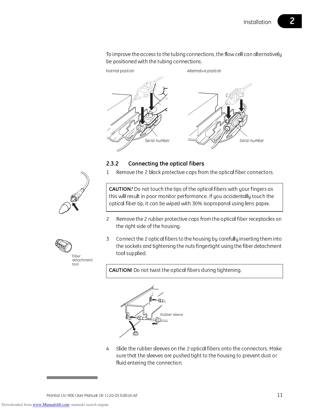
T o improve the access to the t ubing connections, the flow cell can alternativ ely
be positioned with the tubing connections.
2.3.2 Connecting the optical fibers
1 Remove the 2 black protective caps from the optical fiber connectors.
2 Remove the 2 rubber protective caps from the optical fiber recept acles on
the right side of the housing.
3 Connect the 2 opt ical fibers to the housing by carefully inserting them into
the socket s and tightening the nuts fingertight using t he fiber det achment
tool supplied.
4 Slide the rubber sleeves on t he 2 optical fibers onto the connectors. Make
sure that the sleeves are pushed tight to the housing to prevent dust or
fluid entering the connection.
Serial number
Normal position
Serial number
Alternative position
CAUTION
!
Do not touch the tips of the optical fibers with your fingers as
this will result in poor monitor performance. If you accidentally touch the
optical fiber tip, it can be wiped with 30% isopropanol using lens pape
r.
Fiber
detachmen
 Loading...