2 Installation
12
Monitor UV-900 User Manual 18-1120-05 Edition AF
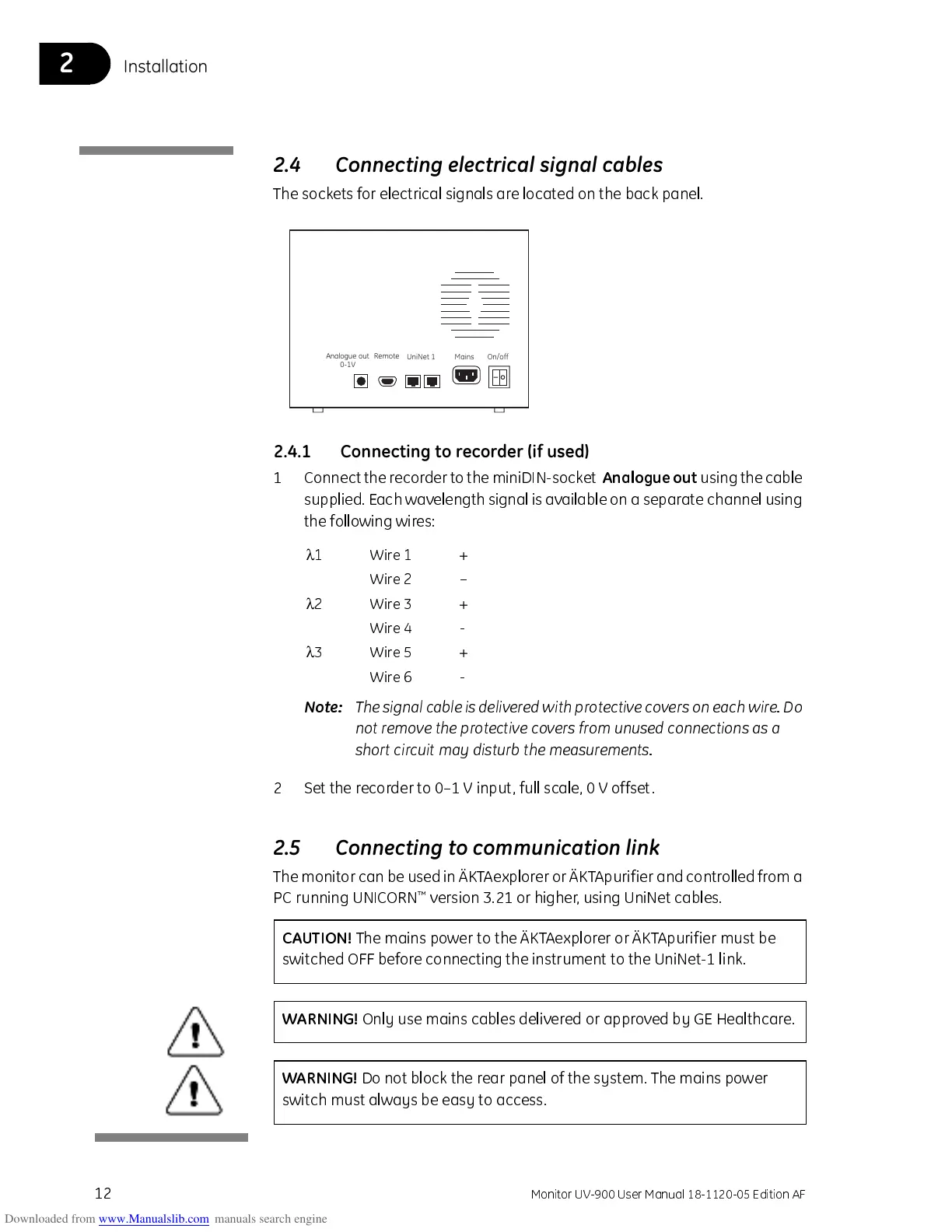
2.4 Connecting electrical signal cables
The sockets for electrical signals are located on the back panel.
2.4.1 Connecting to recorder (if used)
1 Connect the re cor der to the miniD IN-socket
Analogue out
using the cable
supplied. Each wavelength signal is av ailable on a separate channel using
the following wires:
Note:
The signal cable is delivered with protective covers on each wir e. Do
not remove the protective covers from unused connections as a
short circuit may disturb the measurements.
2 Set the recorder to 0–1 V input, full scale, 0 V offset.
2.5 Connecting to communication link
The monitor can be used in ÄKTAexplorer or ÄK T Apuri fier and controlle d from a
PC running UNICORN
™
version 3.21 or higher, using UniNet cables.
Analogue out
0-1V
Remote
UniNet 1 Mains On/off
λ
1 Wire 1 +
Wire 2 –
λ
2 Wire 3 +
Wire 4 -
λ
3 Wire 5 +
Wire 6 -
CAUTI ON!
The mains power to the ÄKTAexplorer or ÄKTApurifier must be
switched OFF before connecting the instrument to the UniNet-1 link.
WARNING!
Only use mains cables delivered or approved by GE Healthcare.
WARNING!
Do not block the rear panel of the system. The mains power
switch must always be easy to access.