Not only can the primary and secondary be connected as a star or a delta, each phase can also be reversed
r
esulting in a large choice of possible connections. In reality, however, only a few of these are used, because we
generally require that the phase shifts between the primary windings and their secondary counterparts be
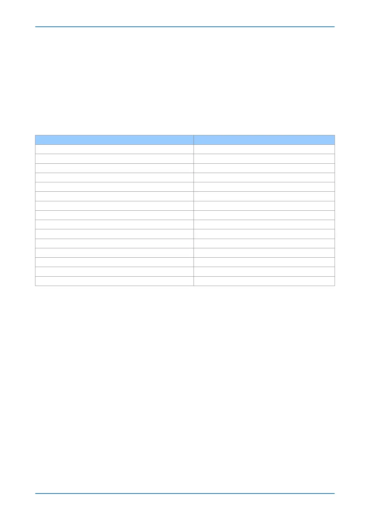
consistent. This reduces the common connection types to those shown in the table below.
You will notice that the naming convention specifying the connection type in the first column also has a number
appended to it. This number, called the clock face vector, or vector group number represents the phase shift
between the current in a low voltage winding with respect to its counterpart on the high voltage winding. This
corresponds to the position of the number of a standard clock face. The table and diagram below shows examples
of connections with the clock vectors Midnight, 1 o’ clock, 6 o’ clock and 11 o’clock, which is equivalent to a phase
shift of 0°, -30°, -180° and +30° respectively.
Vector Group Phase shift
Yy0 0°
Dd0 0°
Dz0 0°
Yd1 -30°
Dy1 -30°
Dz1 -30°
Yd5 -150°
Dy5 -150°
Dz5 -150°
Yy6 180°
Dd6 180°
Dz6 180°
Yd11 +30°
Dy11 +30°
Dz11 +30°
Chapter 6 - Transformer Differential Protection P64x
102 P64x-TM-EN-1.3