B
175/175/30 MVA
230/115/13.8 kV
YNynd1
Phase & amplitude
Correction
+
Zero sequence filtering
BB
D
BB
D
BB
D
Phase & amplitude
Correction
+
Zero sequence filtering
A
C
Protected zone
a
b
c
P645
V03116
a
b
c
Phase & amplitude
Correction
+
Zero sequence filtering
B
B
B
+5% / -15%
19 taps800:5
HV
LV
1200:5
TV
2000:5
Earthing
transformer
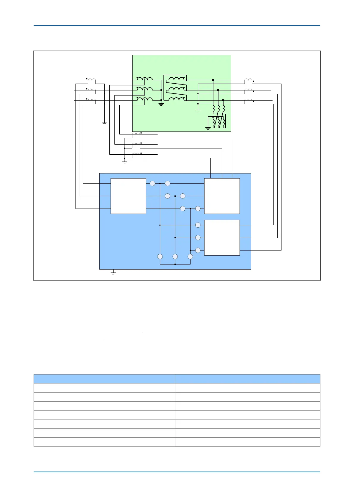
Figure 53: P645 used to protect an autotransformer with loaded delta winding
Since the transformer has an on load tap changer on the HV side, the nominal v
oltage of the HV winding must be
set to the mid tap voltage level. According to the nameplate data, the mid tap voltage is 218.5 kV. The mid tap
voltage can also be calculated as follows:
Mid tap voltage
=
+
−
× =
100
5 15
2
100
230 218 5
( )
. kV
Set the following parameters in the SY
STEM CONFIG column:
Setting in GROUP 1 SYSTEM CONFIG Value
Winding Config HV+LV+TV
Winding Type Auto
HV CT Terminals 00001
LV CT Terminals 10000
TV CT Terminals 00100
Ref Power S 175.00 MVA
Ref Vector Group 0
P64x Chapter 6 - Transformer Differential Protection
P64x-TM-EN-1.3 125