B
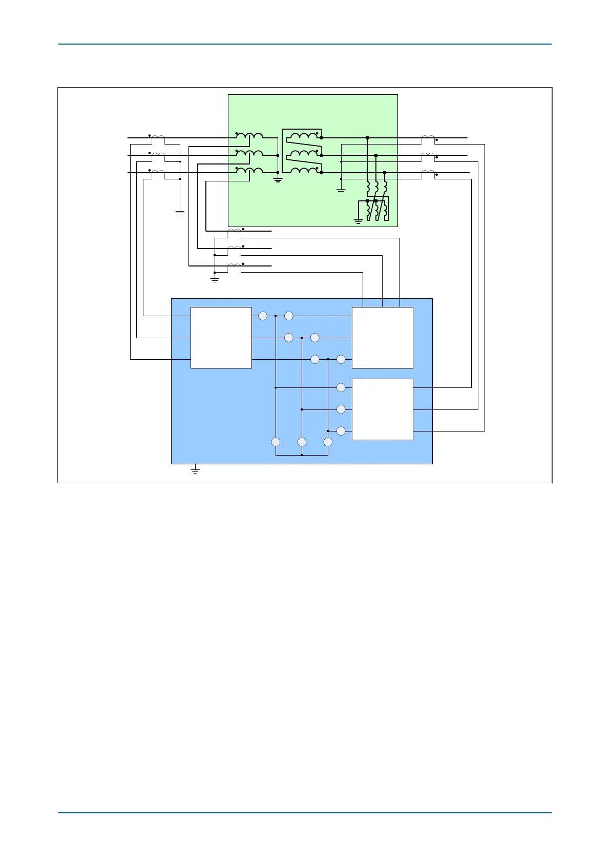
175/175/30 MVA
230/115/13.8 kV
YNynd1
Phase & amplitude
Correction
+
Zero sequence filtering
BB
D
BB
D
BB
D
Phase & amplitude
Correction
+
Zero sequence filtering
A
C
Protected zone
a
b
c
P645
V03116
a
b
c
Phase & amplitude
Correction
+
Zero sequence filtering
B
B
B
+5% / -15%
19 taps800:5
HV
LV
1200:5
TV
2000:5
Earthing
transformer
Figure 64: P645 used to protect an autotransformer with loaded delta winding
Consider the case wher
e an equivalent source and load are connected to the 230 kV terminal and an equivalent
source and load are connected to the 115 kV terminal, but only the load is connected to the 13.8 kV terminal. An
external fault on the 230 kV side would be fed by the source on the 115 kV side. Therefore, the current would
mainly flow from the 115 kV side to the 230 kV side. If the external fault occurs on the 115 kV side, the through-
fault current would flow from the 230 kV side to the 115 kV side. If an external fault occurs on the 13.8 kV side, the
through fault current would flow from the 230 kV and 115 kV sides to the 13.8 kV side. The source and transformer
impedances determine the fault current level.
Set the TF I> Trigger setting above the maximum overload. According to IEEE Std. C57.109-1993, values of 3.5 or
less times normal base current may result from overloads instead of faults. TF I> Trigger may be set to 3.85 pu. If
the monitored current is above this level and no differential element has started, then the I2t is calculated.
To set the TF I2t> Alarm consider the maximum through fault current and the maximum time duration. The
maximum through-fault current may be determined as 1/X, where X is the transformer impedance. This
approximation is valid when the source is strong, so that its impedance is small compared with the transformer
impedance. If the transformer has an impedance of 10%, the maximum through fault current is calculated as:
1/X = 1/0.1 = 10 pu
Chapter 7 - Transformer Condition Monitoring P64x
156 P64x-TM-EN-1.3