5 NEGATIVE SEQUENCE OVERCURRENT PROTECTION
When applying standard phase overcurrent protection, the overcurrent elements must be set significantly higher
than the maximum load curr
ent. This limits the element’s sensitivity. Most protection schemes also use an earth
fault element operating from residual current, which improves sensitivity for earth faults. However, certain faults
may arise which can remain undetected by such schemes. Negative Phase Sequence Overcurrent elements can
help in such cases.
Any unbalanced fault condition will produce a negative sequence current component. Therefore, a negative phase
sequence overcurrent element can be used for both phase-to-phase and phase-to-earth faults. Negative Phase
Sequence Overcurrent protection offers the following advantages:
● Negative phase sequence overcurrent elements are more sensitive to resistive phase-to-phase faults,
where phase overcurrent elements may not operate.
● In certain applications, residual current may not be detected by an earth fault element due to the system
configuration. For example, an earth fault element applied on the delta side of a delta-star transformer is
unable to detect earth faults on the star side. However, negative sequence current will be present on both
sides of the transformer for any fault condition, irrespective of the transformer configuration. Therefore, a
negative phase sequence overcurrent element may be used to provide time-delayed back-up protection for
any uncleared asymmetrical faults downstream.
5.1 NPSOC PROTECTION IMPLEMENTATION
The product provides three overcurrent elements for backup negative phase sequence overcurrent protection.
Each element pr
ovides four-stages of negative sequence overcurrent protection with independent time delay
characteristics. You can select the overcurrent element operating quantity for each of the elements with the
setting cells NPS O/C 1, NPS O/C 2 and NPS O/C 3 in the NEG SEQ O/C column of the relevant settings group. You
can set each element as T1, T2, T3, T4, T5, HV winding, LV winding or TV winding. The HV, LV and TV
windings comprise the vector sums of the CT inputs associated with a particular winding.
Stages 1, 2 provide a choice of operate and reset characteristics, where you can select between:
● A range of standard IDMT (Inverse Definite Minimum Time) curves
● DT (Definite Time)
This is achieved using the cells
● I2>(n) Function for the overcurrent operate characteristic
● I2>(n) Reset Char for the overcurrent reset characteristic (IEEE only)
where (n) is the number of the stage.
The IDMT-capable stages, (1 and 2) also provide a Timer Hold facility. This is configured using the cells
I2>(n) tReset, where (n) is the number of the stage. This is not applicable for curves based on the IEEE standard.
Stages 3 and 4 can have definite time characteristics only.
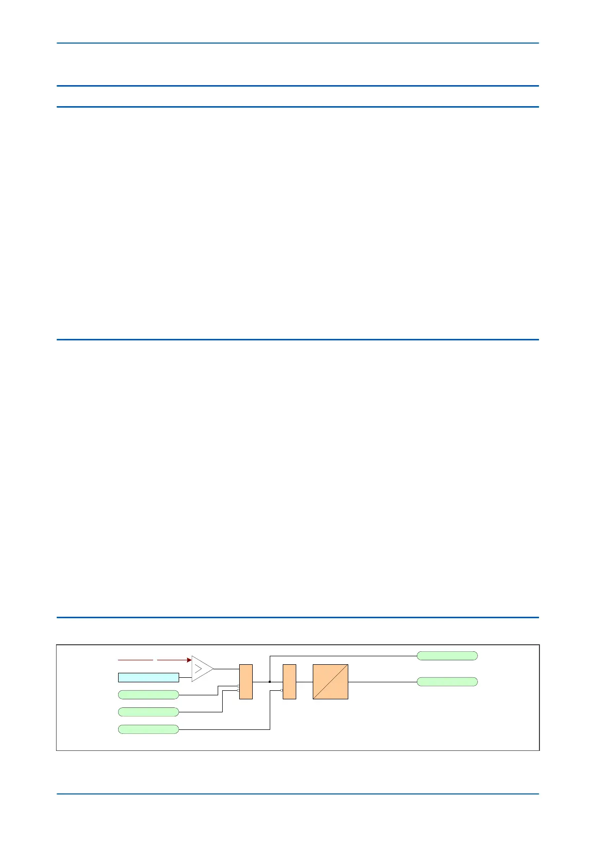
5.2 NON-DIRECTIONAL NPSOC LOGIC
&
NPOC1 I2>1 TBlk
NPOC1 I2>1 Start
NPOC1 I2>1 Trip&
V00674
I2
NPOC1 Inhibit
CTS Block
I2>1 Current Set
IDMT/DT
Figure 99: Negative Sequence Overcurrent logic - non-directional operation
Chapter 9 - Current Protection Functions P64x
212 P64x-TM-EN-1.3