3.4 NON-DIRECTIONAL OVERCURRENT LOGIC
1
&
&
&
1
POC 1 I>1 TBlk
POC1 I>1 Start A
POC1 I>1 Start B
POC1 I>1 Start C
POC 1 I>1 Trip A
POC 1 I>1 Trip B
POC 1 I>1 Trip C
POC1 I>1 Start
POC1 I>1 Trip
&
&
&
POC1 IH2 Any St
IH2 Cross Block
&
POC1 IA2H Start
I> Blocking
&
POC1 IB2H Start
&
V00672
2H Blocks I>1
I> Blocking
2H Blocks I>1
Enabled
IB
POC1 IC2H Start
&
I> Blocking
2H Blocks I>1
IC
Timer Settings
Timer Settings
Timer Settings
IA
I> Threshold*1
I> Threshold*1
I> Threshold*1
IDMT/ DT
IDMT/ DT
IDMT/DT
*1 The threshold settings are influenced by Voltage Control Overcurrent functionality
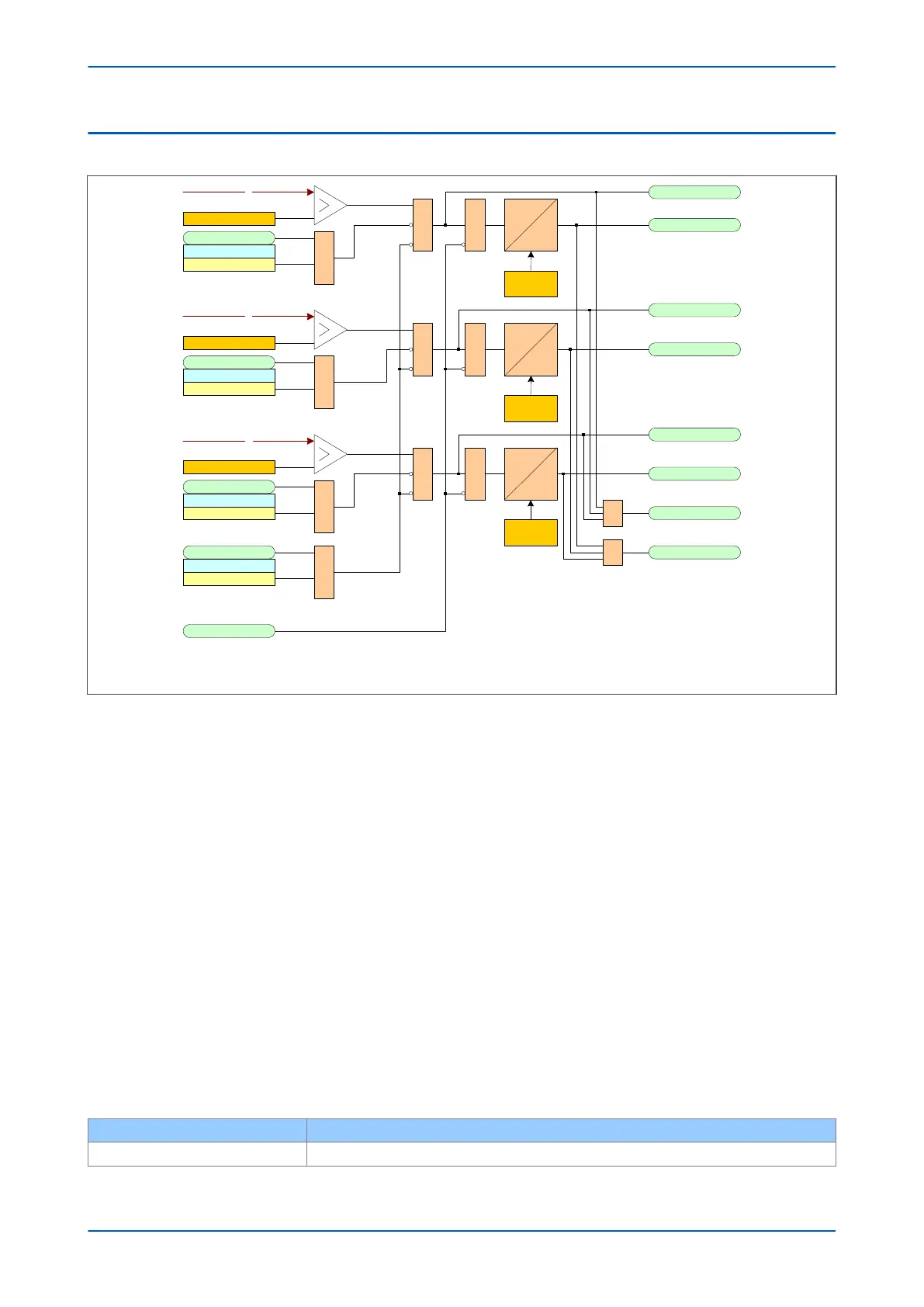
Figure 94: Non-directional overcurrent logic diagram
Phase O
vercurrent Modules are level detectors that detect when the current magnitude exceeds a set threshold.
When this happens, the Phase Overcurrent Module in question issues a signal, which is gated with some blocking
signals to produce the Start signal. This Start signal is gated with other blocking signals and applied to the
IDMT/DT timer module. It is also made available directly to the user for use in the PSL. For each stage, there are
three Phase Overcurrent Modules, one for each phase. The three Start signals from each of these phases are OR'd
together to create a 3-phase Start signal.
The outputs of the IDMT/DT timer modules are the trip signals which are used to drive the tripping output relay.
These tripping signals are also OR'd together to create a 3-phase Trip signal.
The IDMT/DT timer modules can be blocked by:
● A Phase Overcurrent Timer Block (I>(n) Timer Block)
If any one of the above signals is high, or goes high before the timer has counted out, the IDMT/DT timer module is
inhibited (effectively reset) until the blocking signal goes low again. There are separate phase overcurrent timer
block signals, which are independent for each overcurrent stage.
The start signal can be blocked by:
● The Second Harmonic blocking function on a per phase basis or for all three phases. The relevant bits are
set in the I> Blocking cell and this is combined with the relevant second harmonic blocking DDBs.
The G14 Data type is used for the I>Blocking setting:
Bit number I> Blocking function
Bit 0 VTS Blocks I>1
Chapter 9 - Current Protection Functions P64x
204 P64x-TM-EN-1.3