The current loop input starts are mapped internally to the Any S
tart DDB signal.
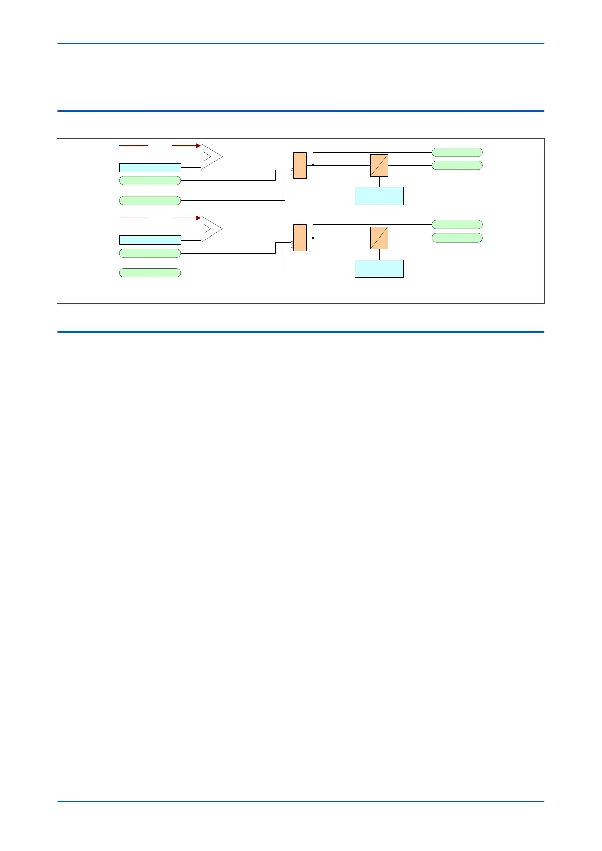
6.2 CURRENT LOOP INPUT LOGIC
V3205
RTD Alarm Set
&
CLI1 I< Fail Alm
CL Card I/P Fail
RTD Value
4-20 mA input only
CLI Alarm Delay
CLI1 Alarm Start
CLI1 Alarm
RTD Trip Set
&
CLI1 I< Fail Alm
CL Card I/P Fail
RTD Value
4-20 mA input only
CLI1 Trip Start
CLI1 Trip
CLI Alarm Delay
Note: This diagram does not show all stages . Other stages follow similar principles.
Figure 68: Current Loop Input logic
6.3 CLO IMPLEMENTATION
Four analog current outputs are provided with ranges of 0 - 1 mA, 0 - 10 mA, 0 - 20 mA or 4 - 20 mA, which can
alleviate the need for separate transducer
s. These may be used to feed moving coil ammeters for measuring
analog quantities, or to feed into a SCADA using an existing analog remote terminal unit (RTU).
The current loop output conversion task runs every 50 ms and the refresh interval for the output measurements is
nominally 50 ms.
You can set the measuring range for each analog output. The range limits are defined by the CLO Minimum and
CLO Maximum settings in the CLIO PROTECTION column for each CL output. This allows you to zoom in and
monitor a restricted range of the measurements with the desired resolution. You can set the voltage and current
quantities to either primary or secondary quantities with the CLO Set Values setting.
The output current of each analog output is linearly scaled to its range limits by the Maximum and Minimum
settings, as shown below:
P64x Chapter 7 - Transformer Condition Monitoring
P64x-TM-EN-1.3 161