CB4 CB5
CB1 CB2
Autotransformer
230/115/13.8 kV
Auxiliary
se
rvices
1
2
V
01236
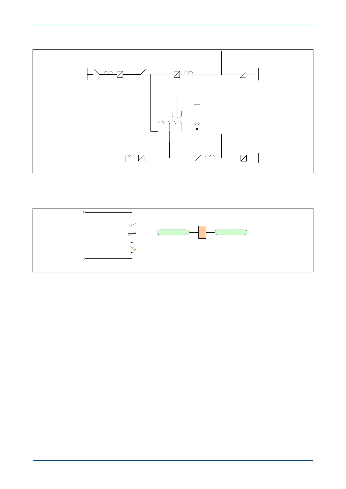
Figure 126: CT input exclusion - 1.5 CB application
The curr
ent transformer associated with CB1 is connected to the T1 CT input. Auxiliary contacts from CB1 isolators
1 and 2 must be connected to an opto-input as follows.
V01233
+V DC
98b - 1
98b - 2
Opto input 14
Opto input 14
1
CT1 Exclu Ena
-V DC
Figure 127: CT input exclusion - auxiliary contact connection
When isolator
s 1 and 2 are open, the opto-input L14 is energized and CT1 Exclu Ena is asserted. To set CT1
Excluded, T1 CT Phase A, B and C undercurrent elements must also be asserted.
P64x Chapter 13 - Monitoring and Control
P64x-TM-EN-1.3 277