4 THROUGH FAULT MONITORING
Through faults are a major cause of transformer damage and failure, as they can stress the insulation and
mechanical integrity of the transformer
. Through-fault monitoring is usually used to tackle this problem. This
mechanism monitors fault currents passing through the transformer, which may significantly exceed its rated
current. The through-fault monitoring mechanism is based on an I
2
t calculation.
According to IEEE C57.109-1993(R2008), mechanical effects are more significant than thermal effects for fault-
current magnitudes near the design capability of the transformer. However, at fault-current magnitudes close to
the overload range, mechanical effects are less important unless the frequency of fault occurrence is high. Note
that mechanical effects are more important in large kVA transformers. The standard states that the maximum
duration limit for the worst case of mechanical duty is 2 s.
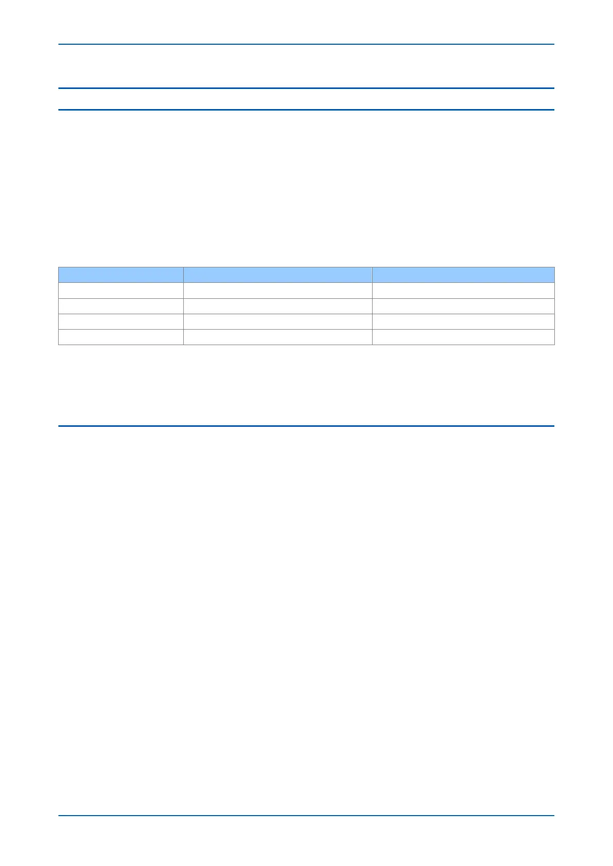
The standard defines the following transformer categories:
Category Single phase (kVA) Three-phase (kVA)
I 5 to 500 15 to 500
II 501 to 1667 501 to 5000
III 1668 to 10000 5001 to 30000
IV Above 10000 Above 30000
Categories I and II consider only the transformer short-circuit impedance, whereas categories III and IV consider
the system short-circuit impedance at the transformer location as well as transformer short-circuit impedance.
The short-circuit impedance is expressed as a percentage of the transformer rated voltage and the rated power of
the transformer.
4.1 THROUGH FAULT MONITORING IMPLEMENTATION
Through-fault monitoring can be enabled with the Thr
ough Fault setting in the TF MONITORING column.
The through-fault current monitoring function monitors the fault current level, the duration of the faulty condition
and the date and time for each through-fault. An I
2
t calculation based on the recorded time duration and
maximum current is performed for each phase.
This calculation is only performed when the current exceeds the TF I> Trigger setting and if the DDB signal Any
Diff Start is NOT asserted. Cumulative stored calculations for each phase are monitored so you can schedule the
transformer maintenance based on this data.
A single-stage alarm is available for through-fault monitoring. The alarm is issued if the maximum cumulative I
2
t in
the three phases exceeds the TF I2t> Alarm setting. A through fault event is recorded if any of the phase currents
is larger than the TF I> Trigger setting. You should always set TF I> Trigger greater than the overload capability of
the transformer.
Chapter 7 - Transformer Condition Monitoring P64x
154 P64x-TM-EN-1.3